Content for TS 23.237 Word version: 18.0.0
0…
4…
5…
5.4…
6…
6.2…
6.2.2…
6.3…
6.3.2…
6.3.2.1.3…
6.3.2.1.7…
6.3.2.1.9…
6.3.2.2…
6.3.2.3…
6.3.2.3.6…
6.3.3…
6.4…
6a…
6a.3…
6a.4…
6a.4.3…
6a.4.5…
6a.4.7…
6a.4a…
6a.5…
6a.6…
6a.7…
6a.8…
6a.9…
6a.10…
6a.11…
6c…
7…
A…
B…
C…
C ATCF in Architectures without IMS-level roaming interfaces
C.1 General
C.2 ATCF enhancements SRVCC Architecture
C.3 ATCF in architectures with Mx as a roaming interface without media anchored in ATGW
$ Change history
C (Normative) ATCF in Architectures without IMS-level roaming interfaces |R16| p. 185
C.1 General p. 185
This Annex provides implementation guidelines for the deployment of ATCF in architectures without IMS-level roaming agreement, and where the P-CSCF and ATCF are located in the HPLMN and MSC is in the VPLMN. Support for architectures without IMS-level roaming interfaces is optional.
C.2 ATCF enhancements SRVCC Architecture p. 185
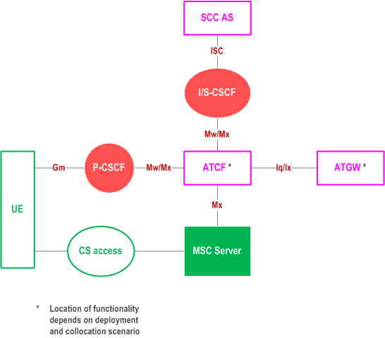
Figure C.2-1 provides the reference architecture for SRVCC using the ATCF enhancements. The Figure only depicts the specific reference points for the ATCF. For other reference points of the general architecture, refer to the reference architecture in clause 5.2 of TS 23.292.

If the ATCF is co-located with P-CSCF, the interface between ATCF and ATGW is Iq, according to TS 23.334.
If the ATCF is co-located with IBCF, the interface between ATCF and ATGW is Ix, according to TS 29.162.
For CS to PS SRVCC scenarios, the interface between MSC Server and ATCF is Mx. This interface does not require roaming level agreements.
SIP signalling related to session transfer is transported from the MSC server in the VLPMN via the Mx reference point and via the IBCF in both VPLMN and the HPLMN to the ATCF in HPLMN. Since Mx is used a s a roaming interface in this case, the support of mid-call features depends on the ability to successfully transport the SIP headers associated with these features between the VPLMN, and the HPLMN and the support in the MSC server and the ATCF.
C.3 ATCF in architectures with Mx as a roaming interface without media anchored in ATGW p. 186
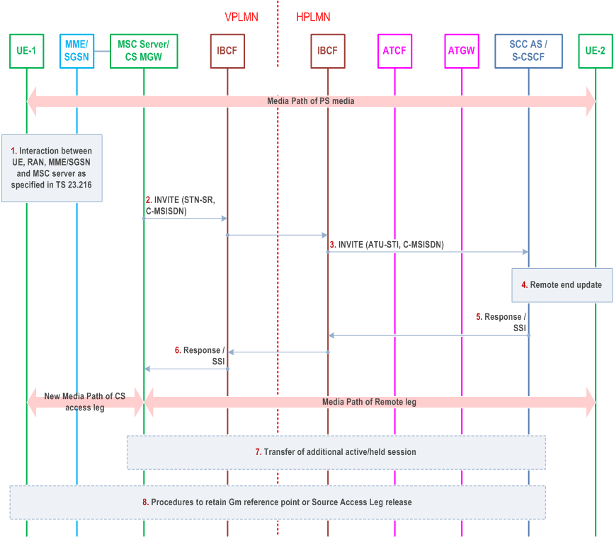
This clause describes the case when the P-CSCF and the ATCF are in the HPLMN in architectures without IMS-level roaming interfaces. In this clause there is no media anchoring in the ATGW. It can be seen that SIP signalling is transported from the MSC server in the VPLMN to the IBCF in the VPLMN via the Mx reference point and in the HPLMN from the IBCF to the ATCF via the Mx reference point as well.

Step 1.
Interaction between UE, RAN, MME/SGSN and MSC Server as specified in TS 23.216. The following step is triggered after the MSC Server has received the PS to CS request from the MME / SGSN and has allocated resources in the RAN.
Step 2.
The MSC Server initiates Access Transfer message and if supported, the MSC Server indicates its capability to support MSC Server assisted mid-call feature. The MSC Server provides all the supported Codecs for voice or voice and video in the Access Transfer message. The Access Transfer message is sent to the IBCF in the VPLMN towards the IBCF in the HPLMN.
Step 3.
The IBCF in the HPLMN sends the Access transfer message via the Mx reference point to the ATCF. The ATCF receives the Access Transfer message and correlates the transferred session using the C-MSISDN. As the media flow has not been anchored in the ATGW, the ATCF forwards the Access Transfer message along with priority indication if received to the SCC AS using the stored ATU-STI. If the MSC Server indicated it supported mid-call feature, it also indicates this in the message to the SCC AS.
Step 4.
The SCC AS correlates the incoming Access Transfer message. As the Session Description has changed, a remote end update is initiated according to clause 6.3.1.5.
Step 5.
The SCC AS sends an Access Transfer response to the ATCF in the HPLMN. In the case MSC Server assisted mid-call feature is supported and used, the SCC AS provides Session State Information (SSI) according to clause 6.3.2.1.4a.
Step 6.
The ATCF forwards the response to the IBCF in the HPLMN and from there to the IBCF in the visited network.
Step 7.
The IBCF in the VPLMN forwards the response to the MSC Server. If the MSC Server receives the Session State Information of more than one active or inactive speech sessions, it initiates Access Transfer towards SCC AS for the additional session according to clause 6.3.2.1.4a.
Step 8.
Procedures according to clause 6.3.2.1.4, steps 4a and 4b are used to handle the cases where the Gm reference point is either retained upon PS handover procedure, not retained upon PS handover, or if there was no other media flow(s) in the IMS session.