Content for TS 33.501 Word version: 19.1.0
1…
4…
5…
5.3…
5.9…
5.10…
6…
6.1.3…
6.1.4…
6.2…
6.2.2…
6.3…
6.4…
6.5…
6.6…
6.7…
6.8…
6.9…
6.10…
6.11
6.12…
6.13
6.14…
6.15…
6.16…
7…
7A…
7A.2.3…
7B…
8…
9…
10…
11…
12…
13…
13.2.2…
13.2.4…
13.3…
13.4…
14…
15…
16…
A…
B…
C…
D…
E…
F…
G…
I…
I.9…
J…
K…
M…
N…
O…
P…
R
S…
T…
U…
V…
W…
X…
Y…
Z…
7B Security for wireline access to the 5G core network
7B.1 General
7B.2 Authentication for 5G-RG
7B.3 Authentication for FN-RG
7B.4 Authentication for UE behind 5G-RG and FN-RG
7B.5 Subscriber privacy for wireline access
7B.6 Subscriber privacy for N5CW over trusted WLAN access
7B.7 Authentication for AUN3 devices behind 5G-RG
7B.7.1 General
7B.7.2 Authentication for AUN3 devices not supporting 5G key hierarchy
7B.7.3 Authentication for AUN3 devices supporting 5G key hierarchy
...
...
7B Security for wireline access to the 5G core network |R16| p. 141
7B.1 General p. 141
To support Wireless and Wireline Convergence for the 5G system, two new network entities, 5G-RG and FN-RG, are introduced in the architecture specificaction TS 23.501.
The 5G-RG acts as a 5G UE and can connect to 5GC via wireline access network (W-5GAN) or via Fixed Wireless Access (FWA). Existing security procedures defined in this document are reused. The 5G-RG also acts as end point of N1 and provides the NAS signaling connection to the 5GC on behalf of the AUN3 devices behind the 5G-RG.
The FN-RG can connect to 5GC via wireline access network (W-5GAN). The W-AGF performs the registration procedure on behalf of the FN-RG. It acts as end point of N1 and provides the NAS signalling connection to the 5GC on behalf of the FN-RG.
A 5G -capable UE can connect to 5GC through an RG that's connected to the 5GC via wireline access network (W-5GAN) or NG-RAN. The UE supports untrusted non-3GPP access and/or trusted non-3GPP access.
7B.2 Authentication for 5G-RG p. 141
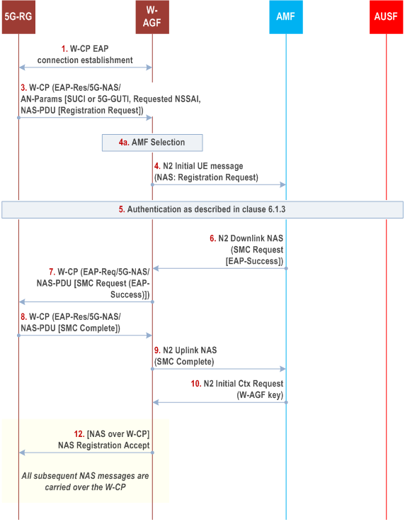
The 5G-RG can be connected to 5GC via W-5GAN, NG RAN or via both accesses. The registration procedure for the 5G-RG connecting to 5GC via NG-RAN is specified in clause 4.11 of TS 23.316. The registration procedure for the 5G-RG connecting to 5GC via W-5GAN is specified in clause 7.2.1 of TS 23.316.
The Untrusted non-3GPP access procedure defined in clause 7.2.1 is used as the basis for registration of the 5G-RG. The 5G-RG shall support both 5G-AKA and EAP-AKA' and it shall be authenticated by the 3GPP home network. The 5G-RG is equivalent to a normal UE.
As 5G-RG is a UE from 5GC point of view, the authentication framework defined in clause 6.1.3 shall be used to authenticate the 5G-RG.
In case of 5G-RG connects to 5GC via 5G-RAN, comparing to clause 6.1, the difference is:
- UE is replaced by 5G-RG.

Step 1.
5G-RG establishes a W-CP connection with a W-5GAN. The detail of connection is out of the scope of 3GPP.
Step 2.
(void)
Step 3.
The 5G-RG shall send a message using W-CP protocol stack that contains a Registration message containing UE security capabilities and the SUCI. If there is an available security context, the 5G-RG shall integrity protect the Registration Request message and shall send the 5G-GUTI instead of SUCI. If the 5G-RG has registered to the same AMF through NG RAN, and if this is the first time that the 5G-RG connects to the 5GC throughW-5GAN, the value of corresponding UL NAS COUNT used for integrity protection is 0; else it can use the existing non-3GPP specific UL NAS COUNT for integrity protection.
Step 4.
The W-AGF shall select an AMF as specified in TS 23.316. The W-AGF shall then forward the Registration Request received from the UE to the selected AMF within an N2 initial UE message
Step 5.
If the AMF receives a 5G-GUTI and the Registration is integrity protected, it may use the security context to verify the integrity protection as describe in clause 6.4.6. If the 5G-RG has registered to the same AMF through NG RAN, and if this is the first time that the AMF receives UE's NAS signalling through wireline access, the value of corresponding UL NAS COUNT used for integrity verification is 0; else it can use the existing non-3GPP specific UL NAS COUNT for integrity verification. If integrity is verified successfully, it indicates that 5G-RG is authenticated by AMF. If integrity is verified successfully and no newer security context has been activated over the NG RAN, then step 8 to step 11 may be skipped. If integrity is verified successfully and a newer security context has been activated over the NG RAN then authentication may be skipped but the AMF shall activate the newer context with a NAS SMC procedure as described in step 8 and onwards. Otherwise, the AMF shall authenticate the 5G-RG.
If the AMF decides to authenticate the 5G-RG, it shall use one of the methods from clause 6.1.3. In this case, the AMF shall send a key request to the AUSF. The AUSF may initiate an authentication procedure as specified in clause 6.1.3. Between AMF and UE (5G-RG), the authentication packets are encapsulated within NAS authentication messages and the NAS authentication messages are carried in N2 signalling between the AMF and W-AGF, and then are encapsulated using W-CP protocol stack message between the W-AGF and the UE (5G-RG).
In the final authentication message from the home network, the AUSF shall send the anchor key KSEAF derived from KAUSF to the SEAF. The SEAF shall derive the KAMF from KSEAF and send it to the AMF which is used by the AMF to derive NAS security keys. If EAP-AKA' is used for authentication as described in clause 6.1.3.1, then the AUSF shall include the EAP-Success. The 5G-RG also derives the anchor key KSEAF and from that key it derives the KAMF followed by NAS security keys. The NAS COUNTs associated with NAS connection identifier "0x02" are set at the 5G-RG and AMF.
Step 6.
The AMF shall send a Security Mode Command (SMC) to the UE (5G-RG) in order to activate NAS security associated with NAS connection identifier "0x02". This message is first sent to W-AGF (within an N2 message). If EAP-AKA' is used for authentication, the AMF shall encapsulate the EAP-Success received from AUSF within the SMC message.
Step 7.
The W-AGF shall forward the NAS SMC to 5G-RG within an EAP-Request/5G-NAS packet.
Step 8.
The W-AGF shall forward the NAS packet containing NAS SMC Complete to the AMF over the N2 interface.
Step 9.
The AMF upon reception of the NAS SMC Complete from the UE (5G-RG) or upon success of integrity protection verification, initiates the NGAP procedure to set up the AN context. AMF shall compute the W-AGF key, KWAGF that is an equivalent to key KN3IWF, using the uplink NAS COUNT associated with NAS connection identifier "0x02" as defined in Annex A.9.
Step 10.
Upon receiving NAS Security Mode Complete, the AMF shall send an N2 Initial Context Setup Request message to the W-AGF. The message contains the KWAGF.
Step 11.
(void)
Step 12.
Upon receiving the NAS Registration Accept message from the AMF, the W-AGF shall forward it to the 5G-RG over the established W-CP. All further NAS messages between the UE and the W-AGF shall be sent over the established W-CP.
7B.3 Authentication for FN-RG p. 143
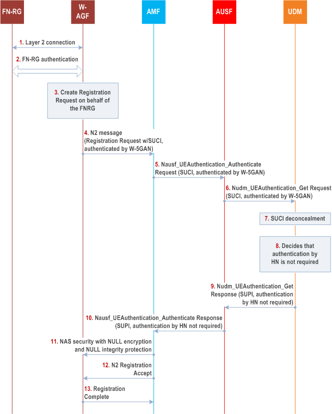
The FN-RG connects to 5GC via W-5GAN, which has the W-AGF function that provides connectivity to the 5GC via N2 and N3 reference points. Since the FN-RG is a non-wireless entity defined by BBF or CableLabs, it doesn't support N1. The W-AGF provides N1 connectivity on behalf of the FN-RG. The authentication method is executed between the FN-RG and AUSF as shown in Figure 7B.c.
The W-AGF may authenticate the FN-RG; this is controlled by local policies.
It is assumed that there is a trust relationship between the wireline operator that manages the W-5GAN and the PLMN operator managing the 5GC. The AMF trusts the W-5GAN based on mutual authentication executed when security is established on the interface between the two using NDS/IP or DTLS.

Step 1.
A layer-2 (L2) connection is established between the FN-RG and the FAGF function in the W-AGF.
Step 2.
The FN-RG is authenticated by the W-AGF. Authentication method used for FN-RG is defined by BBF or CableLabs and out of scope of 3GPP.
Step 3-4.
The W-AGF shall perform initial registration on behalf of the FN-RG. The W-AGF shall generate a Registration Request message and send it to the AMF over N2. The Registration Request message contains the SUCI of the FN-RG. The N2 message contains an indication that the W-AGF has authenticated the FN-RG.
Step 5.
The AMF shall select an AUSF based on the received SUCI. The AMF shall send a Nausf_UEAuthentication_Authenticate Request message to the AUSF. It contains the SUCI of the FN-RG. It also contains the authenticated indication generated by the W-AGF.
Step 6.
The AUSF shall send a Nudm_UEAuthentication_Get Request to the UDM. It contains the SUCI of the FN-RG and the authenticated indication.
Step 7.
The UDM shall invoke the SIDF and maps the SUCI to the SUPI.
Step 8.
The UDM decides, based on the subscription profile of the SUPI and the authenticated indication that authentication has been completed by the W-5GAN, that authentication by the home network is not required for the FN-RG.
Step 9.
The UDM shall send a Nudm_UEAuthentication_Get Response to the AUSF. It contains the SUPI of the FN-RG and an indication that authentication by the home network is not required.
Step 10.
After checking the indication set by the UDM, The AUSF shall not perform authentication and shall send a Nausf_UEAuthentication_Authenticate Response to the AMF. It contains the SUPI of the FN-RG and the indication that authentication by the home network is not required set by the UDM.
This response from AUSF indicates that authentication is not required, and no KSEAF is included.
Step 11.
After checking the indication to make sure that the authentication by the home network is not required, the AMF shall estabilish the NAS security between AMF and W-AGF with NULL encryption and NULL integrity protection.
Step 12.
The AMF shall send Registration Accept message to the W-AGF. This message contains 5G-GUTI and other parameters.
Step 13.
The W-AGF shall send a Registration Complete message back to the AMF. The W-AGF shall store the 5G-GUTI for use in later NAS procedures.
7B.4 Authentication for UE behind 5G-RG and FN-RG p. 145
A UE that is connected to a 5G-RG or FN-RG, can access the 5GC via the N3IWF or via the TNGF.
A UE behind a FN-RG can use the untrusted non-3GPP access procedure as defined in clause 4.12.2.2 of TS 23.502 to access the 5GC via the N3IWF.
A UE behind a 5G-RG can use either the untrusted non-3GPP access as defined in clause 4.12.2.2 of TS 23.502, or trusted N3GPP-access as defined in clause 4.12a.2.2 of TS 23.502.
A UE connecting to the 5G-RG or FN-RG via WLAN supporting IEEE 802.1X can use the NSWO authentication procedure as specified in Annex S of the present document.
When the UE uses untrusted non-3GPP access, the authentication of the UE is as specified in clause 7.2.1.
When the UE uses trusted non-3GPP access, the authentication of the UE is as specified in clause 7A.2.1.
7B.5 Subscriber privacy for wireline access p. 145
The requirements and procedures on the UE related to subscriber privacy in clauses 5.2.5, 6.12 and Annex C are applicable for the 5G-RG.
For a W-AGF representing an FN-RG, the null scheme shall be used to construct the SUCI as described in clauses 4.7.3 and 4.7.4 in TS 23.316.
7B.6 Subscriber privacy for N5CW over trusted WLAN access p. 145
The requirements and procedures on the UE related to subscriber privacy in clauses 5.2.5, 6.12 and Annex C are applicable for the N5CW.
7B.7 Authentication for AUN3 devices behind 5G-RG |R18| p. 145
7B.7.1 General p. 145
An AUN3 device behind 5G-RG, as defined in TS 23.316, shall be registered to the 5GC by the 5G-RG and shall be authenticated by 5GC using EAP-AKA', as specified in RFC 5448.
7B.7.2 Authentication for AUN3 devices not supporting 5G key hierarchy p. 146

Step 1.
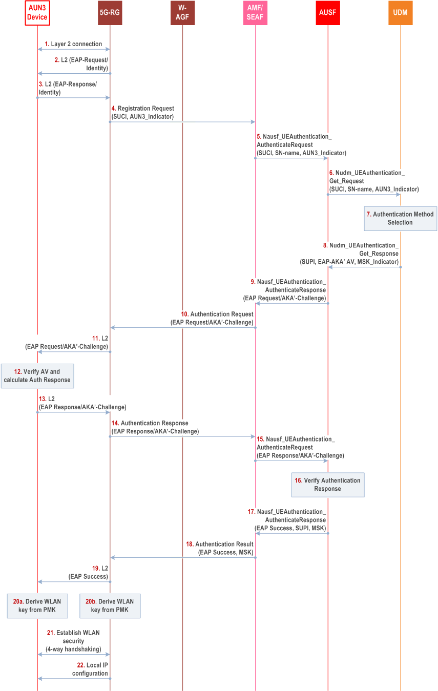
The AUN3 device initiates a layer 2 connection with the 5G-RG either via Ethernet or WLAN. If the layer 2 connection is based on Ethernet, steps 20-21 are skipped.
Step 2.
The 5G-RG shall initiate the EAP authentication procedure by sending an EAP request/Identity to the AUN3 device in a layer 2 frame (e.g., EAPOL).
Step 3.
The AUN3 device shall send back an EAP response/Identity including its Network Access Identifier (NAI) in the form of username@realm. If the AUN3 device supports SUPI privacy, the AUN3 device shall send SUCI in the EAP response/Identity.
Step 4.
The 5G-RG shall construct a SUCI using null-scheme from the NAI-based SUPI if the NAI-based SUPI is received from the AUN3 device in step 3. The 5G-RG shall send a NAS Registration Request message to the AMF, including the SUCI of the AUN3 device and an AUN3 device indicator.
Step 5.
The AMF/SEAF shall select the AUSF based on the SUCI in the received registration request and send to the AUSF a Nausf_UEAuthentication_Authenticate Request message, including the SUCI of the AUN3 device and the AUN3 device indicator.
Step 6.
The AUSF shall send to the UDM a Nudm_UEAuthentication_Get Request message, including the SUCI of the AUN3 device and the AUN3 device indicator.
Step 7.
Upon reception of the Nudm_UEAuthentication_Get Request, the UDM shall invoke the SIDF to map the SUCI to the SUPI and select EAP-AKA' as authentication method based on the SUPI and the AUN3 device indicator. The UDM/ARPF shall generate an authentication vector using the Access Network Identity as the KDF input parameter.
Step 8.
The UDM shall send to the AUSF a Nudm_UEAuthentication_Get Response message, including the EAP-AKA' authentication vector (RAND, AUTN, XRES, CK' and IK'), the SUPI. According to the AUN3 subscription data, the UDM shall also send the MSK indicator to the AUSF to indicate that the AUN3 device does not support the 5G key hirerachy.
Step 9.
The AUSF shall store XRES for future verification. The AUSF shall send the EAP-Request/AKA'-Challenge message to the AMF/SEAF in a Nausf_UEAuthentication_Authenticate Response message.
Step 10.
The AMF/SEAF shall send the EAP-Request/AKA'-Challenge message to the 5G-RG in the NAS Authentication Request message.
Step 11.
The 5G-RG shall send to the AUN3 device the EAP-Request/AKA'-Challenge message encapsulated in a layer 2 (L2) message.
Step 12.
At receipt the EAP-Request/AKA'-Challenge message, the AUN3 device shall verify the message, generate the authentication response, and derive keys as described in RFC 5448.
Step 13.
The AUN3 device shall send the EAP-Response/AKA'-Challenge message to the 5G-RG, encapsulated in a layer 2 message.
Step 14.
The 5G-RG shall send to the AMF/SEAF the EAP-Response/AKA'-Challenge message in an NAS Authentication Response message.
Step 15.
The AMF/SEAF shall send to the AUSF the EAP-Response/AKA'-Challenge message in an Nausf_UEAuthentication_Authenticate Request message.
Step 16.
The AUSF shall verify the AKA'-Challenge message as described in RFC 5448. If successful, based on the MSK indicator received in step 8, the AUSF shall generate the MSK as described in RFC 5448 and the AUSF shall not generate the KAUSF.
Step 17.
The AUSF shall send to the AMF/SEAF an Nausf_UEAuthentication_Authenticate Response message including the EAP-Success, the MSK, and the SUPI.
Step 18.
Based on the received MSK, the AMF shall not generate the KAMF. The AMF shall send EAP-Success and MSK to the 5G-RG in N1 message.
Step 18 could be NAS Security Mode Command or Authentication Result. If Step 18 is a NAS Security Mode Command, it uses NULL encryption and NULL integrity protection, since the NAS security context is not required in this scenario.
Step 19.
The 5G-RG sends to the AUN3 device the the EAP-Success message in a layer 2 frame.
Step 20a-20b.
If the layer 2 connection is over WLAN (IEEE 802.11), the AUN3 device and the 5G-RG use the first 256-bit of the MSK as the PMK, from which the WLAN keys are derived.
Step 21.
The AUN3 and the 5G-RG performs four-way handshaking to establish WLAN secure connection.
7B.7.3 Authentication for AUN3 devices supporting 5G key hierarchy p. 147
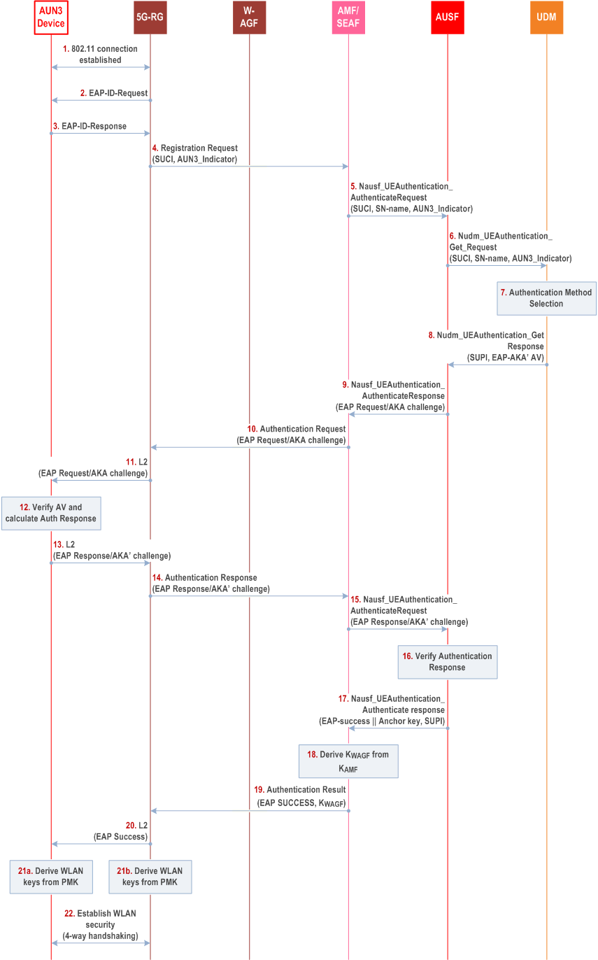
This clause specifies the how an AUN3 device supporting 5G key hierarchy behind 5G-RG shall be registered to the 5GC by the 5G-RG and shall be authenticated by 5GC using EAP-AKA'.

Steps 1-7 are the same as steps 1-7 in clause 7B.7.2.
Step 8.
Steps 9-15 are the same as steps 9-15 in clause 7B.7.2.
The UDM shall send to the AUSF a Nudm_UEAuthentication_Get Response message, including the EAP-AKA' authentication vector (RAND, AUTN, XRES, CK' and IK'), the SUPI.
Step 16.
Step 19 could be NAS Security Mode Command or Authentication Result. If Step 19 is a NAS Security Mode Command, it uses NULL encryption and NULL integrity protection, since the NAS security context is not required in this scenario.
The AUSF shall verify the AKA'-Challenge message as described in RFC 5448. If successful, the AUSF shall generate the KAUSF as defined in clause 6.1.3.1.
Step 17.
The AUSF shall send to the AMF/SEAF an Nausf_UEAuthentication_Authenticate Response message including the EAP-Success, the Anchor key, and the SUPI.
In the final authentication message from the home network, if the AUSF has sent the anchor key KSEAF, the SEAF shall derive the KAMF from KSEAF and send it to the AMF.
Step 18.
The AMF shall derive KWAGF key.
Step 19.
The AMF shall send EAP-Success and KWAGF to the 5G-RG in N1 message.
Step 20.
Step 20 is the same as step 19 in clause 7B.7.2.
Step 21a-21b.
If the layer 2 connection is over WLAN (IEEE 802.11), the AUN3 device and the 5G-RG use KWAGF as the PMK, from which the WLAN keys are derived.
Step 22.
Step 22 is the same as step 21 in clause 7B.7.2.