Content for TS 23.316 Word version: 19.0.0
1…
4…
4.5…
4.7…
4.10…
4.10b…
4.11…
5…
6…
7…
7.2.2…
7.2.3…
7.2.4…
7.3…
7.6…
7.7…
8…
9…
9.5…
10…
A…
C…
7 System procedure
7.1 General
7.2 Connection, Registration and Mobility Management procedures
7.2.1 Registration Management procedures
7.2.1.1 5G-RG Registration via W-5GAN
7.2.1.2 5G-RG Deregistration via W-5GAN
7.2.1.3 FN-RG Registration via W-5GAN
7.2.1.4 FN-RG Deregistration via W-5GAN
...
...
7 System procedure p. 38
7.1 General p. 38
This clause describes the differences in respect the procedures defined in clause 4 of TS 23.502.
7.2 Connection, Registration and Mobility Management procedures p. 38
The listed parameters in the procedures are not exhaustive, but more parameters can be used as described in the protocol specifications.
Where parameters have not been described, the meaning of the parameter is the same as for 3GPP access as described in TS 23.502, TS 24.501, TS 38.413.
7.2.1 Registration Management procedures p. 39
This clause specifies delta for Registration Management procedure defined in clause 4.2 of TS 23.502 for 5G-RG and FN-RG.
7.2.1.1 5G-RG Registration via W-5GAN p. 39
The 5G-RG registration management procedures are followed for both W-5GBAN and W-5GCAN.
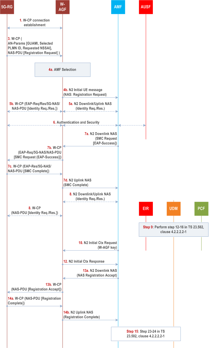
Clause 7.2.1.1 specifies how a 5G-RG can register to 5GC via aW-5GAN. It is based on the Registration procedure specified in clause 4.2.2.2.2 of TS 23.502. The NAS protocol is transported between 5G-RG and W-AGF as documented in BBF TR-456 issue 2 [43] and CableLabs WR-TR-5WWC-ARCH [27]. If the 5G-RG needs to be authenticated, mutual authentication is executed between the 5G-RG and AUSF. The details of the authentication procedure are specified in TS 33.501. In Registration and subsequent Registration procedures via W-5GAN access, the NAS messages are always exchanged between the 5G-RG and the AMF. When possible, the 5G-RG can be authenticated by reusing the existing UE security context in AMF for the 5G-RG.
Figure 7.2.1.1-1 only shows authentication flow using EAP-AKA' (specifically in step 6c, step 7a and step 7b) but other methods are possible: Authentication procedures that 5G-RG and the 5GC shall support, are specified in TS 33.501. Specific EAP authentication methods (see TS 33.501) for 5G-CRG with non-3GPP identities and credentials may be used for isolated network (see TS 33.501).

Step 1.
The 5G-RG connects to a W-5GAN with procedures outside the scope of 3GPP and creates an initial signalling connection using W-CP protocol stack. This connection shall support transfer of AS parameters and NAS messages between 5G-RG and W-AGF.
Step 2.
Void.
Step 3.
The 5G-RG using W-CP protocol stack sends a message that contains the Access Network parameters (GUAMI if available, the selected PLMN or SNPN, Requested NSSAI and Establishment Cause) and a NAS Registration Request message (SUCI or 5G-GUTI as defined in TS 24.501, security parameters/UE security capability, NSSAI parameters, UE MM Core Network Capability, PDU session status, Follow-on request). The Establishment cause provides the reason for requesting a signalling connection with 5GC.
Step 4.
The W-AGF shall select an AMF based on the received AN parameters and local policy, as specified in clause 6.3.5 of TS 23.501. The W-AGF shall then forward the Registration Request received from the UE to the selected AMF within an N2 initial UE message (NAS message, ULI, Establishment cause, UE context request, selected PLMN or SNPN ID).
Step 5.
The selected AMF may decide to request the SUCI by sending a N2 Downlink NAS transport message (NAS Identity Request) message to W-AGF. This NAS message and the response are sent between W-AGF and 5G-RG as described in BBF TR-456 [43] and CableLabs WR-TR-5WWC-ARCH [27]. In this case the RG shall answer with a NAS Identity response.
Step 6.
The AMF may decide to authenticate the 5G-RG by invoking an AUSF. In this case, the AMF shall select an AUSF as specified in clause 6.3.4 of TS 23.501 based on SUPI or SUCI. As defined in 33.501 [11], the AMF transfers the SUCI and the selected PLMN or SNPN ID to the AUSF.
The AUSF executes the authentication of the UE as specified in TS 33.501. The AUSF selects a UDM as described in clause 6.3.8 of TS 23.501 and gets the authentication data from UDM. The authentication packets are encapsulated within NAS authentication messages. Between W-AGF and AMF, the messages are encapsulated within N2 downlink/uplink NAS transport messages. After the successful authentication the AUSF provides relevant security related information to the AMF. If the AMF provided a SUCI to AUSF, the AUSF shall return the SUPI to AMF only after the authentication is successful.
The AMF decides if the Registration Request needs to be rerouted as described in clause 4.2.2.2.3 of TS 23.502, where the initial AMF refers to the AMF.
Step 7a.
If NAS security context does not exist, the NAS security initiation is performed as described in TS 33.501: the AMF initiates NAS Security Mode command. If the 5G-RG had no NAS security context in step 1, the UE includes the full Registration Request message as defined in TS 24.501. If an EAP-AKA' authentication was successfully executed in step 6, the AMF shall encapsulate the EAP-Success received from AUSF within the NAS Security Mode Command message. The message is encapsulated within a N2 downlink NAS transport message.
The AMF initiates a NGAP/N2 procedure to provide the 5G-AN with security context as specified in TS 38.413.
Step 7b.
The W-AGF shall forward the NAS Security Mode Command message to 5G-RG.
Step 7c.
The 5G-RG completes the authentication procedure (if initiated in step 6), creates a NAS security context as defined in TS 33.501 and sends the NAS Security Mode Complete message (IMEISV) to the AMF.
Step 7d.
The W-AGF relays the NAS Security Mode Complete message to the AMF in a N2 Uplink NAS transport message.
Step 8.
[Conditional] The AMF may request the PEI from the 5G-RG as described in clause 4.2.2.2.2, step 11 of TS 23.502.
Step 9.
The AMF performs step 12-16 in clause 4.2.2.2.2 of TS 23.502. At AMF registration to UDM for the 5G-RG, the Access Type non-3GPP access is used. The RAT type used toward PCF and UDM shall indicate wireline access. The AMF determines Access Type and RAT Type based on the Global RAN Node ID associated with the N2 interface.
Step 10.
The AMF sends an N2 Initial Context Setup Request message as defined in TS 38.413 and TS 29.413 possibly including as additional W-AGF specific parameter the RG Level Wireline Access Characteristics.
Step 11a.
Void.
Step 11b.
Void.
Step 12.
W-AGF notifies the AMF that the 5G-RG context was created by sending a N2 Initial Context Setup Response.
Step 13.
The AMF sends N2 Downlink NAS transport with the NAS Registration Accept message (as defined in step 21 in clause 4.2.2.2.2 of TS 23.502) to the W-AGF, which forwards the NAS Registration accept message to the 5G-RG.
Step 14.
[Conditional] The 5G-RG responds with NAS Registration Complete message as described in clause 4.2.2.2.2 of TS 23.502 step 22 and W-AGF forwards the NAS Registration Complete message to AMF in a N2 Uplink NAS transport message. The N2 Uplink NAS transport message to AMF may contain W-AGF identities. The AMF stores the received W-AGF identities in the UE context.
Step 15.
The AMF performs step 23-24 in clause 4.2.2.2.2 of TS 23.502.
7.2.1.2 5G-RG Deregistration via W-5GAN p. 42

Step 1.
The Deregistration procedure is triggered by one of the events:
Step 1a.
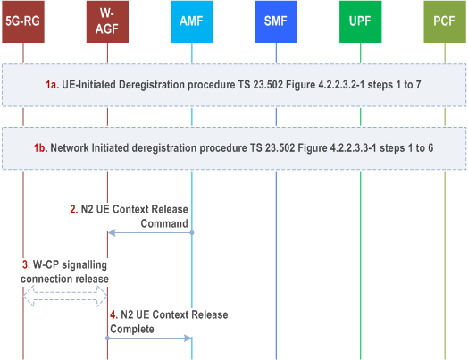
For 5G-RG-initiated Deregistration as in Figure 4.2.2.3.2-1, steps 1 to 7 of TS 23.502.
Step 1b.
For network initiated deregistration as in Figure 4.2.2.3.3-1, steps 1 to 6 of TS 23.502.
If the 5G-RG is in CM-CONNECTED state either in 3GPP access, W-5GAN access or both:
Step 2.
- the AMF may explicitly deregister the 5G-RG by sending a Deregistration request message (Deregistration type, access type set to -W-5GAN) to the 5G-RG as in Figure 4.2.2.3.3-1, step 2 of TS 23.502. The 5G-RG will interpret access type set to non-3GPP as referring to wireline access.
- the UDM may want to request the deletion of the subscribers RM contexts and PDU Sessions with the reason for removal set to subscription withdrawn to the registered AMF as in Figure 4.2.2.3.3-1, step 1 of TS 23.502.
AMF to W-AGF: The AMF sends a N2 UE Context Release Command message to the W-AGF with the cause set to Deregistration to release N2 signalling as defined in clause 4.12.4.2, step 4 of TS 23.502.
Step 3.
The W-AGF may initiate the release of the signalling connection between 5G-RG and W-AGF.
Step 4.
W-AGF to AMF: The W-AGF acknowledges the N2 UE Context Release Command message by sending N2 UE Context Release Complete message to the AMF as defined in clause 4.12.4.2, step 7 of TS 23.502.
7.2.1.3 FN-RG Registration via W-5GAN p. 43
The FN-RG registration management procedures are followed for both W-5GBAN and W-5GCAN. The FN-RG does not support N1 but instead the W-AGF handles the NAS signalling on behalf of the FN-RG as defined by BBF TR-456 [9] and WT-457 [10] for FN-BRG and by WR-TR-5WWC-ARCH [27] for FN-CRG.
When the connectivity is established between the FN-RG and the W-AGF in the W-5GAN, the W-AGF may authenticate the FN-RG; this is controlled by local policies and defined in BBF specifications. Then when the RM state of the FN-RG is "RM-DEREGISTERED" the W-AGF shall perform registration to 5GC as described in this clause, otherwise it performs Service Request as defined in clause 7.2.2.
Once the FN-RG is in RM-REGISTERED and CM-CONNECTED the W-AGF may setup PDU session(s) on behalf of the FN-RG (as described in clause 7.3.4).

Step 1.
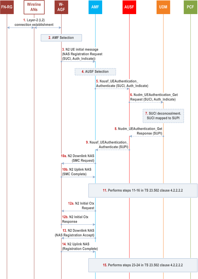
The FN-RG connects to a W-AGF (W-5GAN) via a layer-2 (L2) connection, based on Wireline AN specific procedure.
The FN-RG is authenticated by the W-5GAN based on Wireline AN specific mechanisms.
Step 2.
W-AGF selects an AMF based on the AN parameters and local policy. W-AGF may use the Line ID / HFC identifier provided from the Wireline AN to determine the 5GC and AN parameters to be used for the FN-RG registration. How the W-AGF can determine the necessary 5GC and AN parameters is defined in BBF TR-456 [9], WT-457 [10] or CableLabs WR-TR-5WWC-ARCH [27].
Step 3.
W-AGF performs initial registration on behalf of the FN-RG to the 5GC. The W-AGF sends a Registration Request to the selected AMF within an N2 initial UE message (NAS Registration Request, ULI, Establishment cause, UE context request, Allowed NSSAI, Authenticated Indication).
The NAS Registration Request contains the SUCI or 5G-GUTI of the FN-RG, security parameters/UE security capability, UE MM Core Network Capability, PDU Session Status, Follow-on request, Requested NSSAI. The 5G-GUTI, if available, has been received from the AMF during a previous registration and stored in W-AGF.
The NSSAI parameters are provided based on W-AGF configuration. Based on W-AGF configuration of the 5GC NAS parameters, one or multiple Requested S-NSSAI may be used; e.g. when the W-AGF has been configured to use a specific slice for RG management purposes.
The following differences exist, compared to 5G-RG case:
Step 4.
- The W-AGF use SUCI as defined in clause 4.7.3 and clause 4.7.4.
- The Authenticated Indication indicates to AMF and 5GC that the FN-RG has been authenticated by the access network.
- In the case of a BBF access: the GLI as defined in clause 4.7.8 together with an identifier of the Home network as described in TS 23.003.
- In the case of a Cable access: the GCI as defined in clause 4.7.8 together with an identifier of the Home network as described in TS 23.003.
If the AMF receives a SUCI, the AMF shall select an AUSF as specified in clause 6.3.4 of TS 23.501 based on SUCI. If 5G-GUTI is provided, there is no need to map SUCI to SUPI and steps 5-9 can be skipped.
Step 5.
AMF sends an authentication request to the AUSF in the form of, Nausf_UEAuthentication_Authenticate . It contains the SUCI of the FN-RG. It also contains an indication that the W-5GAN has authenticated the FN-RG.
Step 6.
AUSF selects a UDM as described in clause 6.3.8 of TS 23.501 and sends a Nudm_UEAuthentication_Get Request to the UDM. It contains the SUCI of the FN-RG and indication that the W-5GAN has authenticated the FN-RG.
Step 7.
UDM invokes the SIDF to map the SUCI to a SUPI.
Step 8.
UDM sends a Nudm_UEAuthentication_Get Response to the AUSF. It contains the SUPI corresponding to the SUCI. It also contains an indication that authentication is not required for the FN-RG.
Step 9.
AUSF sends a Nausf_UEAuthentication_Authenticate Response to the AMF. This response from AUSF indicates that authentication is successful. The response contains the SUPI corresponding to the SUCI.
The procedure described in clause 4.2.2.2.3 of TS 23.502 may apply (the AMF decides if the Registration Request needs to be rerouted, where the initial AMF refers to the AMF).
Step 10a.
AMF initiates a NAS security mode command procedure upon successful authentication as defined in TS 33.501.
The NAS security mode command is sent from the AMF to the W-AGF in a N2 Downlink NAS transport message.
Step 10b.
W-AGF responds to the AMF with a NAS Security Mode Complete message in a N2 Uplink NAS transport message. A NAS security context is created between W-AGF and AMF.
Step 11.
The AMF performs steps 11-16 in clause 4.2.2.2.2 of TS 23.502.
The AMF may be configured by local policies to issue EIR check:
Step 12a.
- Only if the PEI is an IMEI; or
- Only if the PEI is an IMEI or a user device trusted MAC address.
Upon receiving NAS Security Mode Complete, the AMF shall send an N2 Initial Context Setup Request message as defined in TS 38.413 and TS 29.413 including possibly as additional W-AGF specific parameter the RG Level Wireline Access Characteristics to the W-AGF.
Step 12b.
W-AGF notifies to the AMF that the FN-RG context was created by sending a N2 Initial Context Setup Response.
Step 13.
The AMF sends the N2 Downlink NAS transport with NAS Registration Accept message (5GS registration result, 5G-GUTI, Equivalent PLMNs or SNPNs, Non-3GPP TAI, Allowed NSSAI, Rejected NSSAI, Configured NSSAI, 5GS network feature support, network slicing indication, Non-3GPP de-registration timer value, Emergency number lists, SOR transport container, NSSAI inclusion mode) to the W-AGF.
The following parameters are ignored by the W-AGF if received from the AMF: Emergency number lists, SOR transport container, NSSAI inclusion mode.
Step 14.
The W-AGF sends a N2 Uplink NAS transport message, including a NAS Registration Complete message, back to the AMF when the procedure is completed. The W-AGF shall store the 5G-GUTI to be able to send it in potential later NAS procedures.
Step 15.
The AMF performs step 23-24 in clause 4.2.2.2.2 of TS 23.502.
The W-AGF may continue by establishing PDU session(s) on behalf of the FN-RG.
7.2.1.4 FN-RG Deregistration via W-5GAN p. 45
The deregistration procedure for the FN-RG is similar to that of 5G-RG described in clause 7.2.1.2 but with the following differences:
- The 5G-RG is replaced with a FN-RG.
- In step 1a and 1b, the W-AGF sends and receives NAS deregistration request/accept messages on behalf of FN-RG.
- UE-initiated deregistration procedure can be initiated by the W-AGF, when it has lost connectivity to the FN-RG.
- For both UE/Network-initiated deregistration procedures, the W-AGF may initiate the release of the signalling connection between the FN-RG and W-AGF based on legacy protocols.