Content for TS 23.316 Word version: 19.0.0
1…
4…
4.5…
4.7…
4.10…
4.10b…
4.11…
5…
6…
7…
7.2.2…
7.2.3…
7.2.4…
7.3…
7.6…
7.7…
8…
9…
9.5…
10…
A…
C…
7.3 Session Management procedures
7.3.0 General
7.3.1 5G-RG Requested PDU Session Establishment via W-5GAN
7.3.1.1 5G-RG PDU Session establishment via W-5GAN
7.3.1.2 PDU Session Establishment with ACS Discovery
7.3.2 5G-RG or Network Requested PDU Session Modification via W-5GAN
7.3.3 5G-RG or Network Requested PDU Session Release via W-5GAN
7.3.4 FN-RG related PDU Session Establishment via W-5GAN
7.3.5 CN-initiated selective deactivation of UP connection of an existing PDU Session associated with W-5GAN Access
7.3.6 FN-RG or Network Requested PDU Session Modification via W-5GAN
7.3.7 FN-RG or Network Requested PDU Session Release via W-5GAN
7.3.8 Session Management Procedures for AUN3 devices
7.3.8.1 PDU Session Establishment of AUN3 device behind 5G-RG
7.3.8.2 PDU Session Modification of AUN3 device behind 5G-RG
7.3.8.3 PDU Session Release of AUN3 device behind 5G-RG
7.4 SMF and UPF interactions
7.5 User Profile management procedures
...
...
7.3 Session Management procedures p. 61
7.3.0 General p. 61
This clause specifies the delta for Session Management procedure defined in clause 4.3 of TS 23.502 for 5G-RG and FN-RG.
7.3.1 5G-RG Requested PDU Session Establishment via W-5GAN p. 61
7.3.1.1 5G-RG PDU Session establishment via W-5GAN p. 61
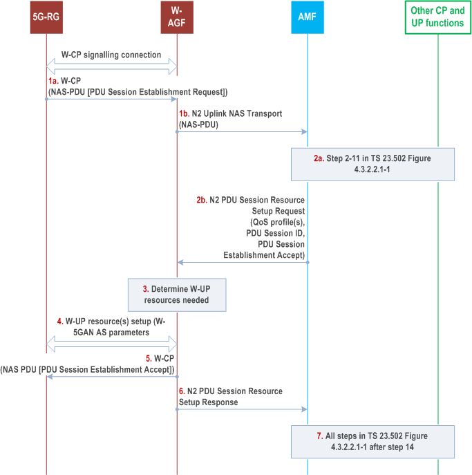
Clause 7.3.1.1 specifies how a 5G-RG can establish a PDU Session via an W-5GAN as well as to hand over an existing PDU Session between 3GPP access and W-5GAN. The procedure applies in non-roaming scenarios.
The PDU Session Establishment procedure specified in clause 4.3.2.2.1 of TS 23.502 applies with the following changes.

Step 1.
The 5G-RG shall send a PDU Session Establishment Request message to AMF as specified in step 1 in clause 4.3.2.2.1 of TS 23.502. This message shall be sent to W-AGF via the W-CP signalling connection and the W-AGF shall transparently forward it in a N2 Uplink NAS transport message (NAS message, User location information, W-AGF identities) to AMF in the 5GC.
The W-AGF identities parameter may be included by the W-AGF and contains a list of Identifiers (i.e. a FQDN and/or IP address(es)) of N3 terminations at W-AGF and can be used by SMF in step 8 in clause 4.3.2.2.1 of TS 23.502 as input to select an UPF.
If the 5G-RG needs Hybrid Access with Multi-Access PDU Session service, the 5G-RG requests a MA PDU Session as defined in clause 4.12. In that case, Steps of clause 4.3.2.2.1 of TS 23.502 apply as modified by clause 4.12.
Step 2a.
Steps 2-11 specified in clause 4.3.2.2.1 of TS 23.502 are executed according to the PDU Session Establishment procedure over 3GPP access with the deviation that in step 3 an additional parameter W-AGF identities received by the AMF from the W-AGF can be sent from AMF to SMF. SMF can use W-AGF identities in step 8 of clause 4.3 of TS 23.502.2.2.1 for UPF selection.
For each QoS Flow, the SMF may request the following to the W-AGF and 5G-RG:
Step 2b.
- ECN marking for L4S at W-AGF in the case of ECN marking for L4S in non-3GPP access as described in clause 5.37.3 of TS 23.501.
- ECN marking for L4S at 5G-RG in UL in the case of ECN marking for L4S in non-3GPP access as described in clause 4.17.2.
As described in steps 11 and 12 of clause 4.3.2.2.1 of TS 23.502, the AMF shall under request of the SMF send a N2 PDU Session Resource Setup Request message to W-AGF to establish the access resources for this PDU Session. The differences with steps 11 and 12 of clause 4.3.2.2.1 of TS 23.502 are:
Step 3.
- The W-AGF shall ignore RSN if received from 5GC.
Based on its own policies and configuration and based on the QoS flows and QoS parameters received in the previous step, the W-AGF shall determine what W-UP resources are needed for the PDU session. For example, the W-AGF may decide to establish one W-UP resource and associate all QoS profiles with this W-UP resource. In this case, all QoS Flows of the PDU Session would be transferred over one W-UP resource.
Step 4a.
The W-AGF sets up the W-UP resources for the PDU session. This step is specified by BBF for W-5BGAN and by CableLabs for W-5GCAN. The access dependent W-UP resource setup procedure shall provide the identity of the PDU Session associated with the W-UP resource. The W-UP resource setup procedure should support to bind W-UP resources to individual QFI(s) as specified in clause 4.4. The W-UP resource request may also contain other access layer information (e.g., VLAN id) specific for the W5GAN.
The 5G-RG may send the established QoS Flows status (active/not active) (ECN marking for L4S at 5G-RG) via N1 SM container.
Step 5.
After all W-UP resources are established, the W-AGF shall forward to 5G-RG via the W-CP signalling connection the PDU Session Establishment Accept message received in step 2b.
Step 6.
The W-AGF shall send to AMF an N2 PDU Session Resource Setup Response (PDU Session ID, AN Tunnel Info, List of accepted/rejected QFI(s), User Plane Security Enforcement Policy Notification, established QoS Flows status (active/not active) (for the following: ECN marking for L4S at W-AGF).
Step 7.
All steps specified in clause 4.3.2.2.1 of TS 23.502 after step 14 are executed according to the PDU Session Establishment procedure over 3GPP access.
7.3.1.2 PDU Session Establishment with ACS Discovery p. 62
This clause specifies how a 5G-RG can establish a PDU Session with ACS Discovery. The ACS discovery mechanism is further specified in clause 9.6.2.
When a 5G-RG performs ACS Discovery during PDU session establishment procedure, the UE Requested PDU Session Establishment via 3GPP Access as described in clause 4.3.2.2.1 of TS 23.502 is used, with the following differences:
- UE is replaced by 5G-RG.
- In FWA scenario the (R)AN is replaced by NG RAN access network, in wireline scenario the (R)AN is replaced by W-5GAN and in HA scenario the (R)AN represents the selected access where the PDU session is being established.
- Step 1. When the 5G-RG sends the PDU session establishment request it includes the DNN which is corresponding to the ACS (per local configuration or per URSP policies). The UE may send in PCO a request to provide ACS information. The UE may include the ACS information request in a DHCP request sent after PDU Session has been established.
- Step 4. The UDM may send the ACS information to the SMF together with the subscription data based on the DNN.
- Step 10. The SMF includes the ACS information in the N1 SM information (PCO) if it has been requested by the UE in step 1 and if it is available at the SMF (if received in Step4).
- Step 19: The 5G-RG may request to receive ACS information via DHCP as described in clause 9.6.2.
- The 5G-RG uses the received ACS information to establish a connection with the ACS.
7.3.2 5G-RG or Network Requested PDU Session Modification via W-5GAN p. 63
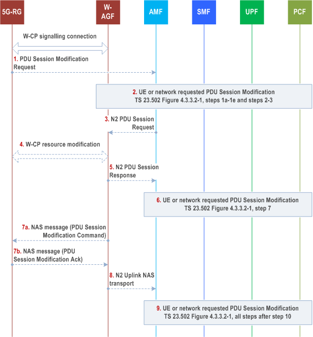
The UE or network requested PDU Session Modification procedure via W-5GAN access is depicted in Figure 7.3.2-1. The procedure applies in non-roaming scenarios.
The procedure below is based on the PDU Session Modification procedure specified in clause 4.3.3.2 of TS 23.502.

Step 1.
If the PDU Session Modification procedure is initiated by the UE, the UE shall send a PDU Session Modification Request message to AMF as specified step 1 in clause 4.3.2.2 of TS 23.502. The message shall be sent to W-AGF via W-CP signalling connection. The W-AGF shall transparently forward the PDU Session Modification Request to AMF/SMF.
Step 2.
The steps 1a (from AMF) to 1e and steps 2-3 as per the PDU Session Modification procedure in clause 4.3.3.2 of TS 23.502 are executed.
For each QoS Flow, the SMF may request the following to the W-AGF and 5G-RG:
Step 3.
- ECN marking for L4S at W-AGF in the case of ECN marking for L4S in non-3GPP access as described in clause 5.37.3 of TS 23.501.
- ECN marking for L4S at 5G-RG in UL in the case of ECN marking for L4S in non-3GPP access as described in clause 4.17.2.
The AMF sends N2 PDU Session Resource Modify Request (N2 SM information received from SMF, NAS message) message to the W-AGF. This step is the same as step 4 in clause 4.3.3.2.
Step 4.
The W-AGF may issue W-CP resource modification procedure (out of scope of 3GPP) with the 5G-RG that is related with the information received from SMF. Based on the N2 SM information received from the SMF, the W-AGF may perform following:
Step 4a.
[Conditional] The W-AGF may decide to create a new W-UP resource for the new QoS Flow(s).
Step 4b.
[Conditional] The W-AGF may decide to add or remove QoS Flow(s) to/from an existing W-UP resource.
Step 4c.
[Conditional] The W-AGF may decide to delete an existing W-UP resource, e.g. when there is no QoS Flow mapped to this W-UP resource.
Step 4d.
[Conditional] The 5G-RG may send the established QoS Flows status (active/not active) (ECN marking for L4S at 5G-RG), PDU Set Based Handling Support Indication via N1 SM container.
Step 5.
The W-AGF acknowledges N2 PDU Session Resource Modify Request by sending a N2 PDU Session Resource Modify Response Message to the AMF to acknowledge the success or failure of the request including established QoS Flows status (active/not active) (for the following: ECN marking for L4S at W-AGF).
Step 6.
Step 7 as per the PDU Session Modification procedure in clause 4.3.3.2 of TS 23.502 is executed.
Step 7.
The W-AGF sends the PDU Session Modification Command to 5G-RG (if received in step 3) and receives the response message from 5G-RG.
Steps 4a/4c and step 7 may happen consecutively. Steps 7b map happen before step 4b/4d.
Step 8.
The W-AGF forwards the NAS message to the AMF.
Step 9.
All the steps after step 10 in clause 4.3.3.2 of TS 23.502 are executed according to the general PDU Session Modification procedure.
7.3.3 5G-RG or Network Requested PDU Session Release via W-5GAN p. 65
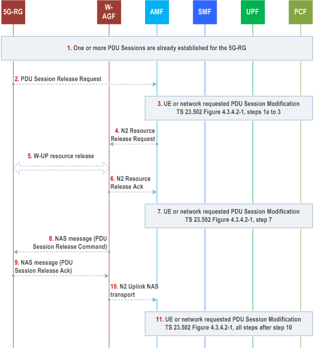
Clause 7.3.3 specifies how a 5G-RG or network can release a PDU Session via a W-5GAN. The 5G-RG requested PDU Session Release procedure via W-5GAN access applies in non-roaming scenarios.
If the 5G-RG is simultaneously registered to a 3GPP access in a PLMN or SNPN different from the PLMN or SNPN of the W-AGF, the functional entities in the following procedures are located in the PLMN or SNPN of the W-AGF.

Step 1.
Steps 5 and 8 may happen consecutively. Step 9 may happen before step 5.
One or more PDU Sessions are already established for the 5G-RG using the procedure described in clause 7.3.1.
Step 2.
The 5G-RG sends a PDU session release request (N1 SM container (PDU Session Release Request), PDU Session ID) to the AMF via the W-AGF as defined in clause 4.3.4 of TS 23.502.
Step 3.
The steps 1a (from AMF) to 3 according to the PDU Session Release procedure defined in clause 4.3.4.2 of TS 23.502 are executed.
Step 4.
This step is the same as step 4 in clause 4.3.4.2 of TS 23.502.
Step 5.
Upon receiving AN session release request message from the AMF, the W-AGF can trigger the release of the corresponding W-UP resource with procedure out of scope of 3GPP.
Step 6.
This step is the same as step 6 in clause 4.3.4.2 of TS 23.502.
Step 7.
Step 7 according to the PDU Session Release procedure defined in clause 4.3.4.2 of TS 23.502 are executed.
Step 8.
The W-AGF delivers the NAS message (N1 SM container (PDU Session Release Command), PDU Session ID, Cause) to the 5G-RG.
Step 9.
The 5G-RG sends a NAS message (N1 SM container (PDU Session Release Ack), PDU Session ID) to the W-AGF.
Step 10.
This step is the same as step 9 in clause 4.3.4.2 of TS 23.502.
Step 11.
The network requested PDU Session Release procedure via W-5GAN access is the same as the network requested PDU Session Release Procedure specified in clause 4.3.4.2 of TS 23.502 for Non-Roaming with the following differences:
All steps after step 9 in the PDU Session Release procedure defined in clause 4.3.4.2 of TS 23.502 are executed.
- The (R)AN corresponds to a W-AGF.
- In step 5, upon receiving N2 SM request to release the AN resources associated with the PDU Session from the AMF, the W-AGF can trigger the release of the corresponding W-UP resource to the 5G-RG as specified in step 5, in Figure 7.3.3-1.
7.3.4 FN-RG related PDU Session Establishment via W-5GAN p. 67
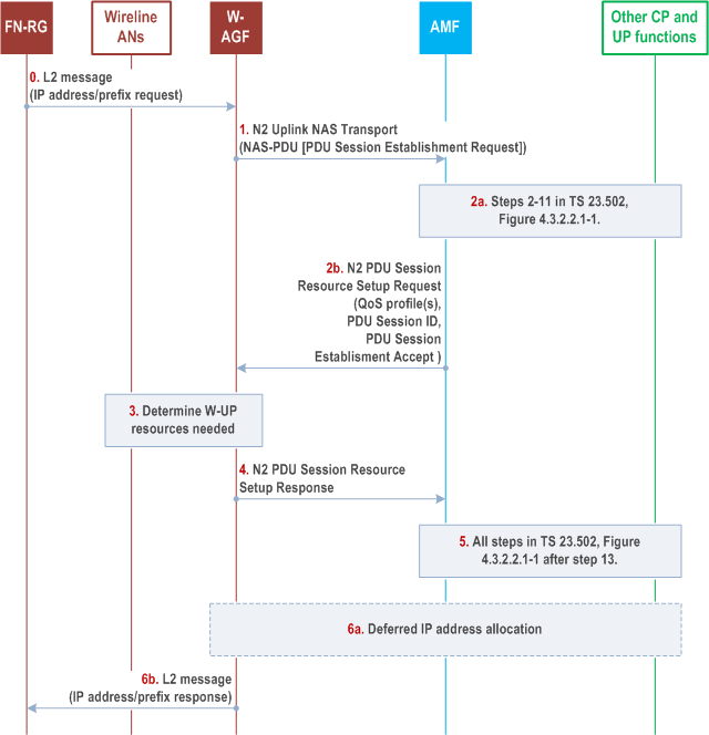
The procedure below is based on the PDU Session Establishment procedure specified in clause 4.3.2.2.1 of TS 23.502.

Step 0.
[Optional] FN-RG sends an IP address/prefix request to the W-AGF via the L2 connection established in clause 7.2.1.3.
Step 1.
After the registration procedure is completed, the W-AGF may establish PDU session(s) on behalf of the FN-RG. The trigger for W-AGF to initiate a PDU establishment process is defined in BBF TR-456 [9], WT-457 [10] and CableLabs WR-TR-5WWC-ARCH [27].
The W-AGF generates a PDU session ID and derives the parameters for the PDU Session (PDU Session type, S-NSSAI, DNN, SSC mode, etc.) based on signalling received from the FN-RG (DHCP, IPv6 RS, etc.), on local configuration, and on information received from the 5GC (e.g. during the Registration procedure or when received URSP rules) and stored on the W-AGF.
If W-AGF has received a DHCPv4/DHCPv6 request from the FN-RG, it may request a PDU Session with deferred IP address allocation.
The W-AGF sends a NAS PDU Establishment Request to the AMF. This request contains the PDU Session ID, and may contain a Requested PDU Session Type, a Requested SSC mode, 5GSM Capability PCO, SM PDU DN Request Container, Number of Packet Filters. In the case of PDU Session Type IPv6 or IPv4v6, the PDU Session Establishment Request may contain an interface identifier of the FN-RG IPv6 link local address associated with the PDU Session.
The W-AGF sends NAS PDU Establishment Request in a N2 Uplink NAS transport message (NAS message, User location information, W-AGF identities).
The W-AGF identities contains a list of Identifiers (i.e. a FQDN and/or IP address(es)) of N3 terminations at W-AGF and can be used by SMF in step 8 in clause 4.3.2.2.1 of TS 23.502 as input to select an UPF.
Step 2a.
The PDU session request is processed in the 5GC as per steps 2-11 of clause 4.3.2.2.1 of TS 23.502. These steps are for UPF selection and resource reservation/allocation in the UPF. With regard to TS 23.502, an additional parameter is sent from AMF to SMF i.e. the list of Identifiers (i.e. a FQDN and/or IP address(es)) of N3 terminations at W-AGF received by the AMF from the W-AGF. The SMF can use it in step 8 for UPF selection as per clause 4.3.2.2.1 of TS 23.502. In the case of PDU Session Type IPv6 or IPv4v6, in step 11 of clause 4.3.2.2.1 of TS 23.502:
Step 2b.
-
The PDU Session Establishment Accept contains the SMF IPv6 link local address associated with the PDU Session if the RAT Type in the Nsmf_
PDUSession_ request equals to wireline access.CreateSMContext - The PDU Session Establishment Accept contains the interface identifier of the FN-RG IPv6 link local address if provided in step 1. Otherwise a SMF allocated FN-RG interface identifier is provided.
The SMF responds via AMF as defined in step 11 of clause 4.3.2.2.1 of TS 23.502 with an N2 PDU Session Resource Setup Request that includes QoS profile(s), PDU Session ID, PDU Session Establishment Accept and the N3 tunnel endpoint information for the UPF. The differences with step 11/12 in clause 4.3.2.2.1 of TS 23.502 are:
Step 3.
- The W-AGF shall ignore RSN if received from 5GC.
Based on its own policies, configuration and based on the QoS flows, QoS parameters received in the previous step, the W-AGF shall determine what W-UP resources are needed for the PDU session.
The W-AGF may, as defined in BBF TR-456 [9], WT-457 [10] and CableLabs WR-TR-5WWC-ARCH [27], perform Access specific resource reservation with the AN, that is, it sets up the W-UP resources for the PDU session.
Step 4.
The W-AGF allocates AN N3 tunnel information for the PDU Session and includes the AN N3 tunnel endpoint information in the N2 PDU Session Resource Setup Response message to the AMF.
Step 5.
The PDU session setup procedure is completed in 5GC. All steps after step 13 as specified in TS 23.502 Figure 4.3.2.2.1-1 are executed.
Step 6a.
If W-AGF requested deferred IP address allocation in step 1 and this was accepted by the network, the W-AGF sends on the user Plane of the PDU Session any DHCP or RS message received beforehand from the FN-RG to the 5GC to obtain the IP address/prefix.
Step 6b.
W-AGF completes the IP address/prefix allocation with the FN-RG via the established L2 connection. If W-AGF did not request deferred IP address allocation in step 1a, the IP address/prefix sent back to the FN-RG is the UE IP address/prefix delivered in NAS message in step 2b. If W-AGF requested deferred IP address allocation in step 1a, the IP address/prefix sent back to the FN-RG is the UE IP address/prefix delivered via deferred IP address allocation procedures in step 6a.
7.3.5 CN-initiated selective deactivation of UP connection of an existing PDU Session associated with W-5GAN Access p. 68
The procedure described in clause 4.3.7 of TS 23.502 (CN-initiated selective deactivation of UP connection of an existing PDU Session) is used for CN-initiated selective deactivation of UP connection for an established PDU Session associated with W-5GAN Access of a 5G-RG/FN-RG in CM-CONNECTED state, with the following exceptions:
- The NG-RAN corresponds to a W-AGF.
- The user plane resource between the 5G-RG/FN-RG and W-AGF, is released not with RRC signalling but with procedure in the scope of BBF/Cablelabs.
7.3.6 FN-RG or Network Requested PDU Session Modification via W-5GAN p. 69
The PDU session modification procedure for the FN-RG is similar to that of 5G-RG described in clause 7.3.2 but with the following differences:
- The 5G-RG is replaced with an FN-RG.
- W-AGF acts on behalf of FN-RG, as an endpoint for N1 signalling. The triggers for initiating PDU Session Modification by the W-AGF are defined by BBF (BBF TR-456 [9]) and Cablelabs.
- If applicable, based on BBF specification BBF TR-456 [9] and Cablelabs specification, in step 1, the W-AGF initiates a PDU Session Modification Request to the AMF on behalf of FN-RG.
- W-AGF may issue L-W-CP resource modification procedure with the FN-RG that is related with the information received from the SMF as in step 4. The actions performed by W-AGF are defined by BBF (BBF TR-456 [9]) and Cablelabs.
- In step 4, L-W-UP resources may be modified by the W-AGF.
- Steps 7a and 7b of clause 7.3.2 are not valid for the FN-RG. The W-AGF creates an Uplink NAS transport message to the AMF, which contains the PDU Session Modification Ack as in step 8.
7.3.7 FN-RG or Network Requested PDU Session Release via W-5GAN p. 69
The PDU session release procedure for the FN-RG is similar to that of 5G-RG described in clause 7.3.3 but with the following differences:
- The 5G-RG is replaced with an FN-RG.
- W-AGF acts on behalf of FN-RG, as an endpoint for N1 signalling.
- In step 2, the W-AGF sends a PDU session release request to the AMF on behalf of FN-RG.
- In step 5, upon receiving AN session release request message from the AMF, the W-AGF can trigger the release of the corresponding L-W-UP resource with procedure in scope of BBF/CableLabs.
- Steps 8 and 9 of clause 7.3.3 are not valid for the FN-RG. The W-AGF creates an Uplink NAS transport message to the AMF, which contains the PDU Session Release Ack as in step 10.
7.3.8 Session Management Procedures for AUN3 devices |R18| p. 69
7.3.8.1 PDU Session Establishment of AUN3 device behind 5G-RG p. 69
This clause specifies the PDU Session Establishment for an AUN3 device served by a 5G-RG as defined in clause 4.10c.
A distinct PDU session is established for each AUN3 device.
After the registration from the AUN3 device, the 5G-RG initiates the establishment of a PDU Session on behalf of the AUN3 device
The PDU Session is established as specified in clause 7.3.1.1 with following differences:
- Steps 1a, 1b and 2b are executed over the AUN3 device's NAS signalling connection and AUN3 device's N2 connection.
-
At step 3 in Figure 4.3.2.2.1 of TS 23.502, the AMF sends the AUN3 SUPI as the SUPI of the PDU session in the Nsmf_
PDUSession_ Request sent to the SMF.CreateSMContext - Steps 5 and 6 are executed over the AUN3 device's N2 connection and AUN3 device's NAS signalling connection.
-
At step 7b in Figure 4.3.2.2.1 of TS 23.502, the SMF sends in the Npcf_
SMPolicyControl_ Request the SUPI of the PDU session (i.e. the AUN3 SUPI).Create
7.3.8.2 PDU Session Modification of AUN3 device behind 5G-RG p. 70
This clause specifies the PDU Session Modification for an AUN3 device served by a 5G-RG as defined in clause 4.5.3.
The PDU Session modification procedure shall use clause 7.3.2 with following differences:
- Step 1 is executed over the AUN3 device's NAS signalling connection and AUN3 device's N2 connection.
- At step 1a in Figure 4.3.3.2-1 of TS 23.502, the AMF sends the AUN3 SUPI as the SUPI of the PDU session.
-
At step 2 in Figure 4.3.3.2-1 of TS 23.502, the SMF sends in the Npcf_
SMPolicyControl_ Request the SUPI of the PDU session (i.e. the AUN3 SUPI).Update - Steps 3 and 5 are executed over the AUN3 device's N2 connection.
- Steps 7 and 8 are executed over the AUN3 device's N2 connection and AUN3 device's NAS signalling connection.
- Only 5GC initiated PDU Session modification is supported in this Release.
7.3.8.3 PDU Session Release of AUN3 device behind 5G-RG p. 70
This clause specifies the PDU Session Release for an AUN3 device served by a 5G-RG as defined in clause 4.10c. This clause applies only to 5G-RG.
AUN3 device may trigger explicit request for connection release, or it may be unreachable (on the 5G-RG to AUN3 device interface). In such scenarios 5G-RG may need to release the PDU session of the AUN3 device.
PDU session release for a specific AUN3 device can also be initiated by the 5GC (e.g., the subscription of the AUN3 device expires).
The PDU Session release procedure shall use clause 7.3.3 with following differences:
- Step 1 is executed over the AUN3 device's NAS signalling connection and AUN3 device's N2 connection. In step 1a of Figure 4.3.4.2-1 of TS 23.502, the 5G-RG sends the PDU Session Release message on the AUN3 device's NAS connection.
- Steps 4 and 6 are executed over the AUN3 device's N2 connection.
- Steps 8-10 are executed over the AUN3 device's N2 connection and AUN3 device's NAS signalling connection.
7.4 SMF and UPF interactions p. 70
SMF and UPF interactions for 5G-RG and FN-RG follow the procedures defined in clause 4.4 of TS 23.502.
7.5 User Profile management procedures p. 70
When 5G-RG or FN-RG is used, the User Profile management procedures in clause 4.5 of TS 23.502 apply, with the differences described below:
- The UE in clause 4.5 of TS 23.502 is replaced by 5G-RG or FN-RG.
- When 5G-RG or FN-RG is connected via W-5GAN, steering of roaming information is not applicable, since roaming is not supported.
- The AMF updates 5G-RG context and FN-RG context stored at W-AGF to modify the RG Level Wireline Access Characteristics.