Content for TS 23.316 Word version: 19.0.0
1…
4…
4.5…
4.7…
4.10…
4.10b…
4.11…
5…
6…
7…
7.2.2…
7.2.3…
7.2.4…
7.3…
7.6…
7.7…
8…
9…
9.5…
10…
A…
C…
7.2.2 Service Request procedures
7.2.2.1 5G-RG Service Request procedure via W-5GAN Access
7.2.2.2 FN-RG Service Request procedure via W-5GAN Access
...
...
7.2.2 Service Request procedures p. 45
7.2.2.1 5G-RG Service Request procedure via W-5GAN Access p. 45
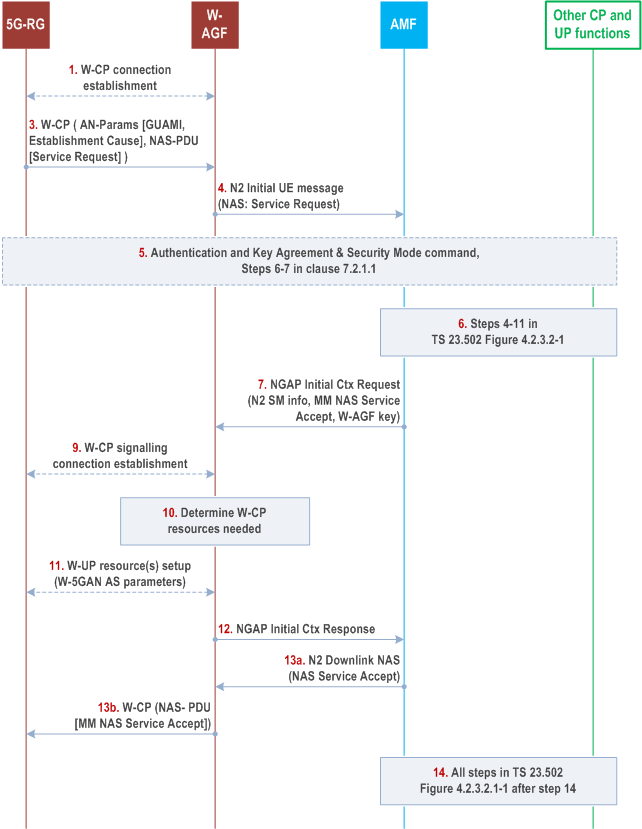
The Service Request procedure via W-5GAN shall be used by a 5G-RG in CM-IDLE state over W-5GAN to request the re-establishment of the NAS signalling connection and the re-establishment of the user plane for all or some of the PDU Sessions which are associated to non-3GPP access.
The Service Request procedure via W-5GAN shall be used by a 5G-RG in CM-CONNECTED state over wireline access to request the re-establishment of the user plane for one or more PDU Sessions which are associated to non-3GPP access.

Step 1.
When the 5G-RG is in CM-CONNECTED state over W-5GAN access and the network receives downlink data for a PDU Session over wireline access that has no user plane connection, the steps 1-4a in clause 4.2.3.3 of TS 23.502 (Network Triggered Service Request) shall be performed with the following exceptions:
The 5G-RG connects to a W-5GAN as described in step 1 of Figure 7.2.1.1-1.
Step 2.
Void.
Step 3.
The 5G-RG using W-CP protocol stack sends a message that contains the Access Network parameters (GUAMI and Establishment Cause) and a NAS Service Request message (List Of PDU Sessions To Be Activated, security parameters, PDU Session status, Uplink Data Status, 5G-S-TMSI). The Establishment cause provides the reason for requesting a signalling connection with 5GC. In this release of the specification no Selected PLMN or SNPN parameter is sent by a 5G RG.
Step 4.
The W-AGF shall then forward the Service Request received from the 5G-RG to the selected AMF within an N2 initial UE message (NAS Service Request message, User Location Information, Establishment cause, UE context request).
Step 5.
The AMF may initiate NAS authentication/security procedure as defined in step 6 and step 7 in clause 7.2.1.1.
If the UE in CM-IDLE state triggered the Service Request to establish a signalling connection only, after successful establishment of the signalling connection the UE and the network can exchange NAS signalling and steps 6 and 14 are skipped.
Step 6.
Steps 4-11 in TS 23.502 Figure 4.2.3.2-1 are performed for each requested PDU session user plane.
For each QoS Flow, the SMF may request the following to the W-AGF and 5G-RG:
Step 7.
- ECN marking for L4S at W-AGF in the case of ECN marking for L4S in non-3GPP access as described in clause 5.37.3 of TS 23.501.
- ECN marking for L4S at 5G-RG in UL in the case of ECN marking for L4S in non-3GPP access as described in clause 4.17.2.
(If the 5G RG was CM-IDLE) AMF sends an N2 Initial Context Setup Request message (N2 SM information received from SMF(s), RG Level Wireline Access Characteristics, GUAMI, Allowed NSSAI, UE security capability, Security Key, Trace Activation, Masked IMEISV).
If the 5G RG was CM-CONNECTED the AMF sends N2 SM information received from SMF(s).
The W-AGF ignores any UE security capability received in a N2 Initial Context Setup Request message.
Step 8.
Void.
Step 9.
[Conditional, if the 5G RG was CM-IDLE] A signalling connection using W-CP protocol stack is established between the 5G-RG and W-AGF.
Steps 10 and 11 are carried out for each PDU Session indicated in step 7
Step 10.
Based on its own policies and configuration and based on the QoS flows and QoS parameters received in the previous step, the W-AGF shall determine what W-UP resources are needed for the PDU session.
Step 11.
The W-AGF sets up the W-UP resources for the PDU session. This step is specified by BBF for W-5BGAN and by CableLabs for W-5GCAN. The access dependent W-UP resource setup procedure shall map to the identity of the PDU Session associated with the W-UP resource.
The 5G-RG may send the established QoS Flows status (active/not active) (ECN marking for L4S at 5G-RG) via N1 SM container.
Step 12.
W-AGF notifies the AMF that the 5G-RG context was created by sending a N2 Initial Context Setup Response (N2 SM information that provides AN Tunnel Info, List of accepted QoS Flows, List of rejected QoS Flows per PDU Session ID for PDU Sessions whose UP connections are activated, established QoS Flows status (active/not active) (for the following: ECN marking for L4S at W-AGF)).
Step 13.
AMF sends NAS Service Accept via W-AGF to the 5G-RG.
Step 14.
All steps after step 14 in TS 23.502 Figure 4.2.3.2-1 are performed for each requested PDU Session user plane.
- The (R)AN corresponds to an W-AGF.
- The UE corresponds to the 5G-RG.
- In step 4a of clause 4.2.3.3 of TS 23.502, the steps 2b-6 in Figure 7.3.1.1-1 are performed to establish the W-UP resources and to establish N3 tunnel. In steps 2b and 6, no NAS message is exchanged with the UE.
7.2.2.2 FN-RG Service Request procedure via W-5GAN Access p. 47
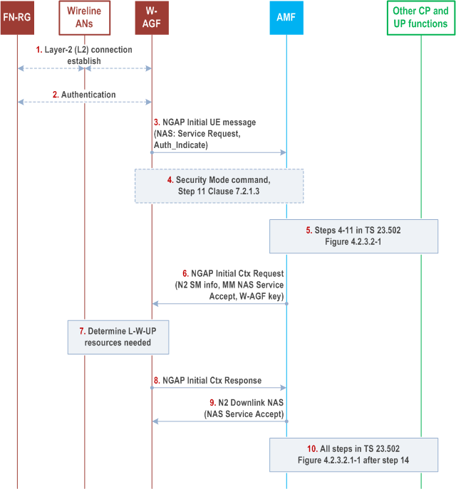
The Service Request procedure via W-5GAN shall be used by a W-AGF when the CM state in W-AGF for a FN-RG is CM-IDLE over W-5GAN to request the re-establishment of the NAS signalling connection and the re-establishment of the user plane for all or some of the PDU Sessions which are associated to non-3GPP access.
The Service Request procedure via W-5GAN shall be used by a W-AGF when the CM state in W-AGF for a FN-RG is CM-CONNECTED over wireline access to request the re-establishment of the user plane for one or more PDU Sessions which are associated to non-3GPP access.

Step 1.
When the FN-RG CM state in W-AGF is CM-CONNECTED over W-5GAN access and the network receives downlink data for a PDU Session over wireline access that has no user plane connection, the steps 1-4a in clause 4.2.3.3 of TS 23.502 (Network Triggered Service Request) shall be performed with the following exceptions:
If the FN-RG has lost the L2 connection with W-AGF, the FN-RG connects to a W-AGF (W-5GAN) via a layer-2 (L2) connection, based on Wireline AN specific procedure.
Step 2.
If step 1 was done, the FN-RG may be authenticated by the W-5GAN based on Wireline AN specific procedure.
Step 3.
The W-AGF shall then send a Service Request to the selected AMF within an N2 initial UE message (NAS Service Request message, User Location Information, Establishment cause, UE context request, Auth_Indicate).
Step 4.
The AMF may initiate NAS authentication/security procedure as defined in steps 5-10 in clause 7.2.1.3.
If the W-AGF triggered the Service Request to establish a signalling connection only, after successful establishment of the signalling connection the W-AGF and the network can exchange NAS signalling and steps 5 and 10 are skipped.
Step 5.
Steps 4-11 in TS 23.502 Figure 4.2.3.2-1 are performed for each requested PDU session user plane.
Step 6.
(If the FN-RG CM state was CM-IDLE) AMF sends an N2 Initial Context Setup Request message (N2 SM information received from SMF(s), RG Level Wireline Access Characteristics, GUAMI, Allowed NSSAI, UE security capability, Security Key, Trace Activation, Masked IMEISV).
If the FN-RG CM state in W-AGF was CM-CONNECTED the AMF sends N2 SM information received from SMF(s).
The W-AGF ignores any UE security capability received in a N2 Initial Context Setup Request message.
Step 7 is carried out for each PDU Session indicated in step 6.
Step 7.
Based on its own policies and configuration and based on the QoS flows and QoS parameters received in the previous step, the W-AGF shall determine what W-UP resources are needed for the PDU session.
The W-AGF may perform BBF specific resource reservation with the AN, that is, it sets up the L-W-UP resources for the PDU session. This step is specified by BBF for W-5GBAN and by CableLabs for W-5GCAN.
Step 8.
W-AGF notifies the AMF that the FN-RG context in W-AGF was created by sending a N2 Initial Context Setup Response (N2 SM information that provides AN Tunnel Info, List of accepted QoS Flows, List of rejected QoS Flows per PDU Session ID for PDU Sessions whose UP connections are activated).
Step 9.
AMF sends NAS Service Accept to W-AGF.
Step 10.
All steps after step 14 in Figure 4.2.3.2-1 of TS 23.502 are performed for each requested PDU session user plane.
- The (R)AN corresponds to an W-AGF.
- The UE corresponds to the FN-RG.
- In step 4a, the steps 6-10 in Figure 7.2.2.2-1 are performed to establish the L-W-UP resources and to establish N3 tunnel. In step 6, the AMF does not send the NAS Service Accept message to the UE.