Content for TS 23.316 Word version: 19.0.0
1…
4…
4.5…
4.7…
4.10…
4.10b…
4.11…
5…
6…
7…
7.2.2…
7.2.3…
7.2.4…
7.3…
7.6…
7.7…
8…
9…
9.5…
10…
A…
C…
6 Control and User Plane Protocol Stacks
6.1 General
6.2 Control Plane Protocol Stacks for W-5GAN
6.2.1 Control Plane Protocol Stacks between the 5G-RG and the 5GC
6.2.2 Control Plane Protocol Stacks between the FN-RG and the 5GC
6.3 User Plane Protocol Stacks for W-5GAN
6.3.1 User Plane Protocol Stacks between the 5G-RG and the 5GC
6.3.2 User Plane Protocol Stacks between the FN-RG and the 5GC
...
...
6 Control and User Plane Protocol Stacks p. 36
6.1 General p. 36
This clause specifies the protocol stacks between 5G-RG, FN-RG and 5GS entities for supporting W-5GAN.
6.2 Control Plane Protocol Stacks for W-5GAN p. 36
6.2.1 Control Plane Protocol Stacks between the 5G-RG and the 5GC p. 36

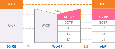
The control plane protocol stack between 5G-RG and AMF is defined in Figure 6.2.1-1.
For W-5GBAN, the W-CP protocol stack between 5G-BRG and W-AGF is defined in BBF TR-456 [9]. For W-5GCAN, the W-CP protocol stack between 5G-CRG and W-AGF is defined in WR-TR-5WWC-ARCH [27].
The protocol stack between 5GC/AMF and W-AGF is defined in clause 8 of TS 23.501.
The W-CP protocol stack:
- supports transfer of NAS signalling between the 5G-RG and the W-AGF;
- supports to carry AS parameters (e.g. SUCI or 5G-GUTI, Requested NSSAI and Establishment Cause) and NAS packets;
- supports the setup, modification and removal of at least one W-UP resource per PDU session;
- may support the setup, modification and removal of multiple W-UP resources per PDU session.
6.2.2 Control Plane Protocol Stacks between the FN-RG and the 5GC p. 37

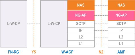
The control plane protocol stack between FN-RG and AMF is defined in Figure 6.2.2-1. The W-AGF acts as an N1 termination point on behalf of FN-RG.
For W-5GBAN, the L-W-CP protocol stack, between FN-BRG and W-AGF is defined in BBF TR-456 [9] and WT-457 [10]. For W-5GCAN, the L-W-CP protocol stack between FN-CRG and W-AGF is defined in WR-TR-5WWC-ARCH [27].
6.3 User Plane Protocol Stacks for W-5GAN p. 37
6.3.1 User Plane Protocol Stacks between the 5G-RG and the 5GC p. 37

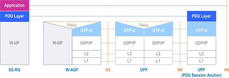
The user plane protocol stack between 5G-RG and UPF is defined in Figure 6.3.1-1.
For W-5GBAN, the W-UP protocol stack between 5G-BRG and W-AGF is defined in BBF TR-456 [9]. For W-5GCAN, the W-UP protocol stack between 5G-CRG and W-AGF is defined in WR-TR-5WWC-ARCH [27].
The protocol stack between 5GC/UPF and W-AGF is defined in clause 8 of TS 23.501.
For the W-UP protocol stack:
- W-UP supports at least one W-UP resource per PDU session. This will be the default W-UP resource.
- W-UP may support multiple W-UP resources per PDU session and associate different QoS profiles (QFIs) to different W-UP resources.
- W-UP supports transmission of uplink and downlink PDUs according to clause 4.5.
- W-UP supports access specific QoS parameters that can be mapped from 3GPP QoS parameters (e.g.5QI, RQI) received from the 5GC.
6.3.2 User Plane Protocol Stacks between the FN-RG and the 5GC p. 38

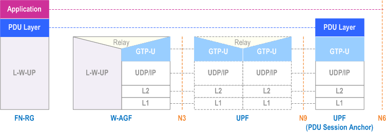
The user plane protocol stack between FN-RG and UPF is defined in Figure 6.3.2-1.
For W-5GBAN, the L-W-UP protocol stack between FN-BRG and W-AGF is defined in BBF TR-456 [9] and WT-457 [10]. For W-5GCAN, the L-W-UP protocol stack between FN-CRG and W-AGF is defined in WR-TR-5WWC-ARCH [27].