Content for TS 23.316 Word version: 19.0.0
1…
4…
4.5…
4.7…
4.10…
4.10b…
4.11…
5…
6…
7…
7.2.2…
7.2.3…
7.2.4…
7.3…
7.6…
7.7…
8…
9…
9.5…
10…
A…
C…
4.10 UE behind 5G-RG and FN-RG p. 24
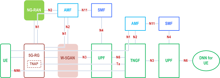
An RG connecting via W-5GAN or NG-RAN access towards 5GC can provide connectivity for a UE behind the RG to access an N3IWF or TNGF. It is assumed that the UE is 5GC capable, i.e. supports untrusted non-3GPP access and/or trusted non-3GPP access. This allows the RG, W-5GAN and the RG's connectivity via 5GC to together act as untrusted/trusted N3GPP access to support UEs behind the RG.
When FN-RG/5G-RG is serving a UE, the control and user plane packets of the UE is transported using a FN-RG/5G-RG IP PDU session and then from PSA UPF of that PDU session to an N3IWF or TNGF. A single FN-RG/5G-RG IP PDU session can be used to serve multiple UEs.
Figure 4.10-1 shows the non-roaming architecture for a UE, behind a 5G-RG, accessing the 5GC via TNGF where the combination of 5G-RG, W-5GAN and UPF serving the 5G-RG is acting as a trusted Non-3GPP access network.
Figure 4.10-2a shows the non-roaming architecture for a UE, behind a FN-RG, accessing the 5GC via N3IWF.
Figure 4.10-2b shows the non-roaming architecture for a UE, behind a 5G-RG, accessing the 5GC via N3IWF.
Annex A shows the non-roaming architecture for a UE, behind a FN-RG/5G-RG, accessing the 5GC via N3IWF where the combination of FN-RG/5G-RG, W-5GAN and UPF serving the 5G-RG is acting as an untrusted Non-3GPP access network.

The 5G-RG can be connected to 5GC via W-5GAN, NG-RAN or via both accesses. The UE can be connected to 5GC via trusted non-3GPP access with 5G-RG acting as TNAP, NG-RAN or via both accesses.


The FN-RG can only be connected to 5GC via W-5GAN. The 5G-RG can be connected to 5GC via W-5GAN, NG-RAN or via both accesses. The UE can be connected to 5GC via untrusted non-3GPP access with FN-RG/5G-RG acting as WLAN access point, NG-RAN or via both accesses.
The TNGF and Ta reference point are defined in TS 23.501. In addition to the requirements described in TS 23.501, the Ta reference point should be able to carry the TNAP ID to the TNGF.
Support of NSWO for 3GPP UE behind an RG is specified in clause 4.10d.
A 5G-RG acting as a TNAP shall provide its TNAP ID. to the TNGF and the TNGF provides this TNAP ID as part of ULI (User Location Information) sent to the 5GC; this information is propagated to the PCF that may use it to determine PCC rules depending on whether an UE is using a 5G-RG as a host or as a guest.
4.10a Non-5G capable device behind 5G-CRG and FN-CRG p. 25
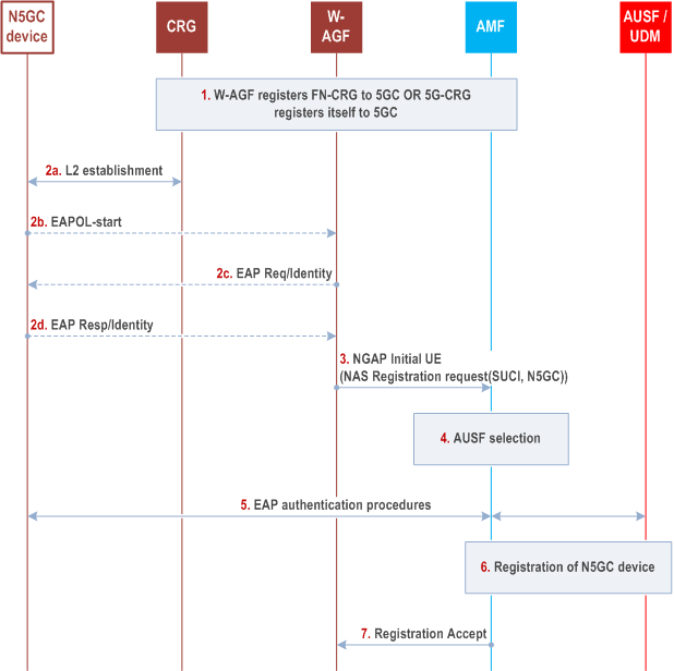
For isolated 5G networks (i.e. roaming is not considered) with wireline access, non-5G capable (N5GC) devices connecting via W-5GAN can be authenticated by the 5GC using EAP based authentication method(s) as defined in TS 33.501. The following call flow describes the overall registration procedure of such a device.
Roaming is not supported for N5GC devices.
The usage of N5GC device correspond to a subscription record in UDM/UDR that is separate from that of the CRG.

Step 1.
After successful registration, PDU Session establishment/modification/release procedure specified in clause 7.3.4, 7.3.6, and 7.3.7 apply with the difference as below:
The W-AGF registers the FN-CRG to 5GC as specified in clause 7.2.1.3 or the 5G-CRG registers to 5GC as specified in clause 7.2.1.1.
Step 2.
The CRG is configured as L2 bridge mode and forwards any L2 frame to W-AGF. 802.1x authentication may be triggered. This can be done either by N5GC device sending a EAPOL-start frame to W-AGF or W-AGF receives a frame from an unknown MAC address.
How the CRG is configured to work in L2 bridge mode and how the W-AGF is triggered to apply procedures for N5GC devices is defined in CableLabs WR-TR-5WWC-ARCH [27].
The N5GC device send an EAP-Resp/Indentity including its Network Access Identifier (NAI) in the form of username@realm.
Step 3.
W-AGF, on behalf of the N5GC device, sends a NAS Registration Request message to AMF with a device capability indicator that the device is non-5G capable. For this purpose, the W-AGF creates a NAS Registration Request message containing a SUCI. The W-AGF constructs the SUCI from the NAI received within EAP-Identity from the N5GC device as defined in TS 33.501.
Over N2 there is a separate NGAP connection per N5GC device served by the W-AGF.
When it provides (over N2) ULI to be associated with a N5GC device, the W-AGF builds the N5GC's ULI using the GCI (see clause 4.7.9) of the CRG connecting the N5GC device.
Step 4.
AMF selects a suitable AUSF as specified in clause 6.3.4 of TS 23.501.
Step 5.
EAP based authentication defined in TS 33.501 is performed between the AUSF and N5GC device.
Once the N5GC device has been authenticated, the AUSF provides relevant security related information to the AMF. AUSF shall return the SUPI (this SUPI corresponds to a NAI that contains the username of the N5GC device and a realm as defined in TS 33.501) to AMF only after the authentication is successful.
Step 6.
The AMF performs other registration procedures as required (see clause 4.2.2.2.2 of TS 23.502).
When providing a PEI for a N5GC device, the W-AGF shall provide a PEI containing the MAC address of the N5GC device. The W-AGF may, based on operator policy, encode the MAC address of the N5GC device using the IEEE Extended Unique Identifier EUI-64 format (see IEEE Publication [41]).
Step 7.
The AMF sends Registration Accept message to W-AGF.
Once the registration procedure is completed, the W-AGF requests the establishment of a PDU Session on behalf of the N5GC device. Only one PDU session per N5GC device is supported. The procedure is the same as the PDU Session establishment procedure specified in clause 7.3.4 with the difference as below:
- FN-RG is replaced by N5GC device.