Content for TS 38.300 Word version: 18.4.0
1…
4…
4.7…
5…
5.3…
5.4…
6…
6.2…
6.6…
7…
8…
9…
9.2.2…
9.2.2.5…
9.2.3…
9.2.3.2…
9.2.3.3…
9.2.4…
9.2.6…
9.3…
10…
11…
15…
15.5…
16…
16.2…
16.3…
16.4…
16.8…
16.9…
16.10…
16.12…
16.12.5…
16.12.6…
16.12.6.3
16.12.7
16.13…
16.14…
16.15…
16.18…
16.19…
16.21…
16.21.3…
17…
18…
19
20…
21…
A…
B…
C…
G…
A QoS Handling in RAN
A.1 PDU Session Establishment
A.2 New QoS Flow with RQoS
A.3 New QoS Flow with Explicit RRC Signalling
A.4 New QoS Flow with Explicit NAS Signalling
A.5 Release of QoS Flow with Explicit Signalling
A.6 UE Initiated UL QoS Flow
...
...
A QoS Handling in RAN p. 247
A.1 PDU Session Establishment p. 247
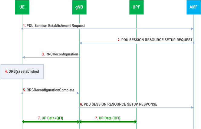
The following Figure shows an example message flow for a PDU session establishment. NAS procedures details between gNB and 5GC can be found in TS 23.501, TS 23.502 and TS 38.413.
Step 1.
UE requests a PDU session establishment to AMF.
Step 2.
AMF sends a PDU SESSION RESOURCE SETUP REQUEST message to gNB, which includes the NAS message to be sent to the UE with NAS QoS related information.
Step 3.
gNB sends an RRCReconfiguration message to UE including the configuration of at least one DRB and the NAS message received at Step 2.
Step 4.
UE establishes the DRB(s) for the new PDU session and creates the QFI to DRB mapping rules.
Step 5.
UE sends an RRCReconfiguration Complete message to gNB.
Step 6.
gNB sends a PDU SESSION RESOURCE SETUP RESPONSE message to AMF.
Step 7.
User Plane Data can then be exchanged between UE and gNB over DRB(s) according to the mapping rules and between UPF and gNB over the tunnel for the PDU session. QFI marking over Uu is optional (see clause 12) while QFI marking over NG-U is always present.
A.2 New QoS Flow with RQoS p. 247
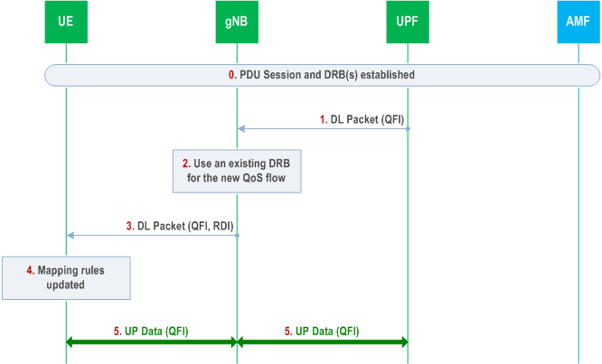
The following Figure shows an example message flow when RQoS is used for a new QoS flow. In this example, the gNB receives from UPF a first downlink packet associated with a QFI for which the QoS parameters are known from the PDU session establishment, but for which there is no association to any DRB yet in AS.
Step 0.
PDU session and DRB(s) have been already established.
Step 1.
gNB receives a downlink packet with a new QFI from UPF.
Step 2.
gNB decides to send the new QoS flow over an existing DRB.
Step 3.
gNB sends the DL packet over the selected DRB with the new QFI and RDI set in the SDAP header.
Step 4.
UE identifies the QFI and RDI in the received DL packet and the DRB on which the packet was received. The AS mapping rules are then updated accordingly.
Step 5.
User Plane Data for the new QoS flow can then be exchanged between UE and gNB over the DRB according to the updated mapping rules and between UPF and gNB over the tunnel for the PDU session.
A.3 New QoS Flow with Explicit RRC Signalling p. 248
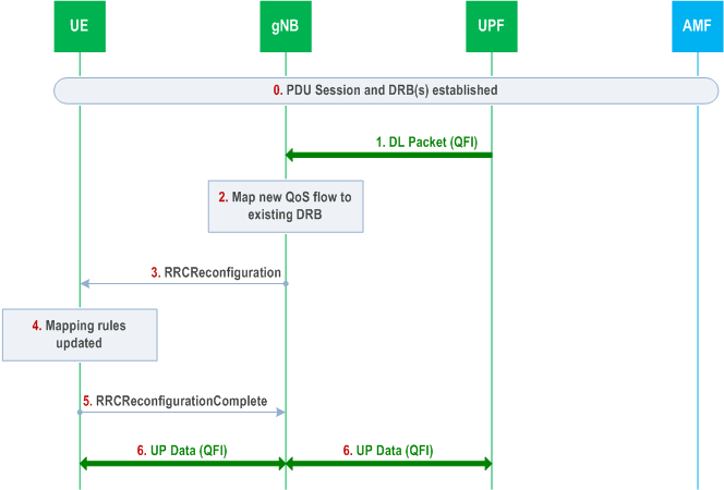
The following Figure shows an example message flow when explicit RRC signalling is used for a new QoS flow. In this example, the gNB receives from UPF a first downlink packet associated with a QFI, for which the QoS parameters are already known from the PDU session establishment, but for which there is no association to any DRB yet in AS.
Step 0.
PDU session and DRB(s) have been already established.
Step 1.
gNB receives a downlink packet with a new QFI from UPF.
Step 2.
gNB decides to send the new QoS flow over an existing DRB using explicit RRC signalling for updating the AS mapping rules.
Step 3.
gNB sends an RRCReconfiguration message to UE with the new QFI to DRB mapping rule. gNB may also decide to update the DRB configuration if required to meet the QoS requirements for the new QoS Flow.
Step 4.
UE updates the QFI to DRB mapping rules and configuration (if received).
Step 5.
UE sends an RRCReconfigurationComplete message to gNB.
Step 6.
User Plane Data for the new QoS flow can then be exchanged between UE and gNB over the DRB according to the updated mapping rules and between UPF and gNB over the tunnel for the PDU session.
A.4 New QoS Flow with Explicit NAS Signalling p. 249
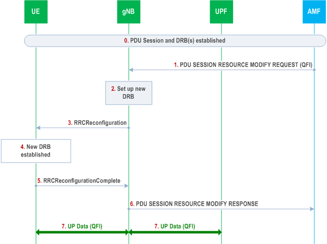
The following Figure shows an example message flow when the gNB receives a new QoS flow establishment request from CN that involves NAS explicit signalling. The QoS flow establishment request provides the gNB and UE with the QoS parameters for the QFI. In this example, the gNB decides to establish a new DRB (rather than re-use an existing one) for this QoS flow and provides the mapping rule over RRC signalling. NAS procedures details between gNB and 5GC can be found in TS 23.501, TS 23.502 and TS 38.413.
Step 0.
PDU session DRB(s) have been already established.
Step 1.
gNB receives a PDU SESSION RESOURCE MODIFY REQUEST message from AMF for a new QoS flow.
Step 2.
If gNB cannot find an existing DRB to map this new QoS flow, it decides to establish a new DRB.
Step 3.
gNB sends an RRCReconfiguration message to UE including the DRB configuration with the new QFI to DRB mapping rule and the NAS message received at step 1.
Step 4.
UE establishes the DRB for the new QoS flow associated with this PDU session and updates the mapping rules.
Step 5.
UE sends an RRCReconfigurationComplete message to gNB.
Step 6.
gNB sends a PDU SESSION RESOURCE MODIFY RESPONSE message to AMF.
Step 7.
User Plane Data can then be exchanged between UE and gNB over DRB(s) according to the mapping rules and between UPF and gNB over the tunnel for the PDU session.
A.5 Release of QoS Flow with Explicit Signalling p. 250
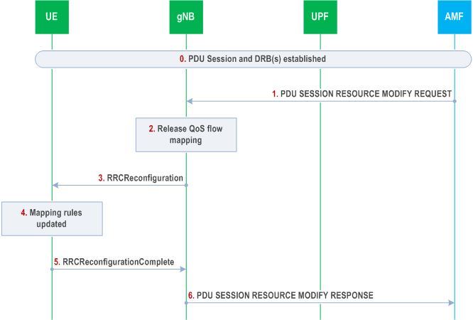
The following Figure shows an example message flow when the gNB receives a request to release a QoS flow from CN that involves explicit NAS signalling. NAS procedures details between gNB and 5GC can be found in TS 23.501, TS 23.502 and TS 38.413.
Step 0.
PDU session and DRB(s) have been already established.
Step 1.
gNB receives a PDU SESSION RESOURCE MODIFY REQUEST message from AMF to release a QoS flow.
Step 2.
The gNB decides to release corresponding the QFI to DRB mapping rule. Since the DRB also carries other QoS flows, the DRB is not released.
Step 3.
gNB sends an RRCReconfiguration message to UE to release the QFI to DRB mapping rule.
Step 4.
UE updates the AS QFI to DRB mapping rules to release this QFI to DRB mapping rule.
Step 5.
UE sends an RRCReconfigurationComplete message to gNB.
Step 6.
gNB sends a PDU SESSION RESOURCE MODIFY RESPONSE message to AMF.
A.6 UE Initiated UL QoS Flow p. 250
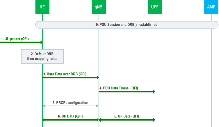
The following Figure shows an example message flow when the UE AS receives an UL packet for a new QoS flow for which a QFI to DRB mapping rule does not exist.
Step 0.
PDU session and DRBs (including a default DRB) have been already established.
Step 1.
UE AS receives a packet with a new QFI from UE NAS.
Step 2.
UE uses the QFI of the packet to map it to a DRB. If there is no mapping of the QFI to a DRB in the AS mapping rules for this PDU session, then the packet is assigned to the default DRB.
Step 3.
UE sends the UL packet on the default DRB. The UE includes the QFI in the SDAP header.
Step 4.
gNB sends UL packets to UPF and includes the corresponding QFI.
Step 5.
If gNB wants to use a new DRB for this QoS flow, it sets up one. It can also choose to move the QoS flow to an existing DRB using RQoS or RRC signalling (see clause A.2 and A.3).
Step 6.
User Plane Data for the new QoS flow can then be exchanged between UE and gNB over the DRB according to the updated mapping rules and between UPF and gNB over the tunnel for the PDU session.