Content for TS 38.300 Word version: 18.4.0
1…
4…
4.7…
5…
5.3…
5.4…
6…
6.2…
6.6…
7…
8…
9…
9.2.2…
9.2.2.5…
9.2.3…
9.2.3.2…
9.2.3.3…
9.2.4…
9.2.6…
9.3…
10…
11…
15…
15.5…
16…
16.2…
16.3…
16.4…
16.8…
16.9…
16.10…
16.12…
16.12.5…
16.12.6…
16.12.6.3
16.12.7
16.13…
16.14…
16.15…
16.18…
16.19…
16.21…
16.21.3…
17…
18…
19
20…
21…
A…
B…
C…
G…
4.7 Integrated Access and Backhaul
4.7.1 Architecture
4.7.2 Protocol Stacks
4.7.3 User-plane Aspects
4.7.3.1 Backhaul transport
4.7.3.2 Flow and Congestion Control
4.7.3.3 Uplink Scheduling Latency
4.7.4 Signalling procedures
4.7.4.1 IAB-node Integration
4.7.4.2 IAB-node Migration
4.7.4.3 Topological Redundancy
4.7.4.4 Backhaul RLF Recovery
4.7.4.5 OTA timing synchronization
4.7.4.6 Inter node discovery
4.7.5 Mobile IAB
4.7.5.1 General
4.8 Non-Public Networks
4.9 Network-Controlled Repeaters
4.9.1 Architecture
4.9.2 Capabilities
4.9.3 Signalling procedures
4.9.4 OAM aspects
4.9.5 Network-controlled repeater management
...
...
4.7 Integrated Access and Backhaul |R16| p. 30
4.7.1 Architecture p. 30
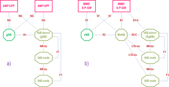
Integrated access and backhaul (IAB) enables wireless relaying in NG-RAN. The relaying node, referred to as IAB-node, supports access and backhauling via NR. The terminating node of NR backhauling on network side is referred to as the IAB-donor, which represents a gNB with additional functionality to support IAB. Backhauling can occur via a single or via multiple hops. The IAB architecture is shown in Figure 4.7.1-1.
The IAB-node supports the gNB-DU functionality, as defined in TS 38.401, to terminate the NR access interface to UEs and next-hop IAB-nodes, and to terminate the F1 protocol to the gNB-CU functionality, as defined in TS 38.401, on the IAB-donor. The gNB-DU functionality on the IAB-node is also referred to as IAB-DU.
In addition to the gNB-DU functionality, the IAB-node also supports a subset of the UE functionality referred to as IAB-MT, which includes, e.g., physical layer, layer-2, RRC and NAS functionality to connect to the gNB-DU of another IAB-node or the IAB-donor, to connect to the gNB-CU on the IAB-donor, and to the core network.
The IAB-node can access the network using either SA mode or EN-DC. In EN-DC, the IAB-node connects via E-UTRA to a MeNB, and the IAB-donor terminates X2-C as SgNB (TS 37.340).
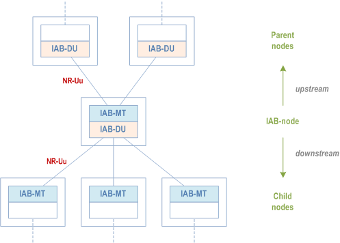
All IAB-nodes that are connected to an IAB-donor via one or multiple backhaul hops and controlled by this IAB-donor via F1AP and/or RRC form an IAB topology with the IAB-donor as its root (Figure 4.7.1-2). In this IAB topology, the neighbour node of the IAB-DU or the IAB-donor-DU is referred to as the child node and the neighbour node of the IAB-MT is referred to as the parent node. The direction toward the child node is referred to as downstream while the direction toward the parent node is referred to as upstream. The IAB-donor performs centralized resource, topology and route management for its IAB topology.
4.7.2 Protocol Stacks p. 32
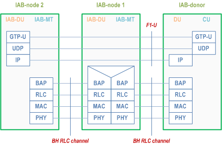
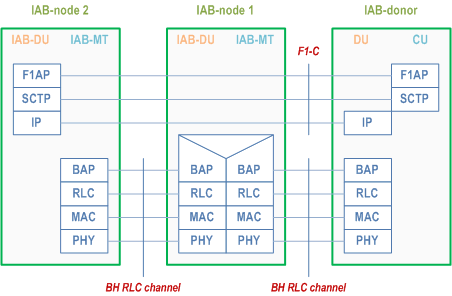
Figure 4.7.2-1 shows the protocol stack for F1-U and Figure 4.7.2-2 shows the protocol stack for F1-C between IAB-DU and IAB-donor-CU. In these Figures, F1-U and F1-C are carried over two backhaul hops.
F1-U and F1-C use an IP transport layer between IAB-DU and IAB-donor-CU as defined in TS 38.470. F1-U and F1-C need to be security-protected as described in TS 33.501 (the security layer is not shown in the Figures 4.7.2-1/2).
On the wireless backhaul, the IP layer is carried over the Backhaul Adaptation Protocol (BAP) sublayer, which enables routing over multiple hops. The IP layer can also be used for non-F1 traffic, such as OAM traffic as defined in TS 38.401.
On each backhaul link, the BAP PDUs are carried by BH RLC channels. Multiple BH RLC channels can be configured on each BH link to allow traffic prioritization and QoS enforcement. The BH-RLC-channel mapping for BAP PDUs is performed by the BAP entities on each IAB-node and the IAB-donor-DU.
Protocol stacks for an IAB-donor with split gNB architecture are specified in TS 38.401.
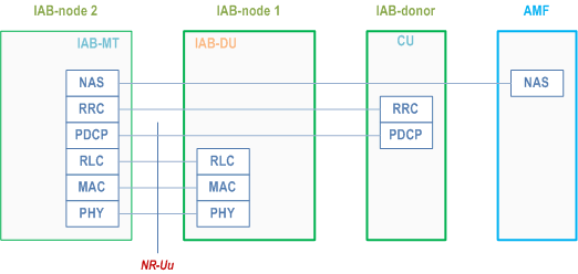
The IAB-MT further establishes SRBs (carrying RRC and NAS) with the IAB-donor-CU. For IAB-nodes operating in EN-DC, the IAB-MT establishes one or more DRBs with the eNB and one or more DRBs with the IAB-donor-CU, which can be used, e.g., to carry OAM traffic. For SA mode, the establishment of DRBs is optional. These SRBs and DRBs are transported between the IAB-MT and its parent node over Uu access channel(s). The protocol stacks for the SRB is shown in Figure 4.7.2-3.
4.7.3 User-plane Aspects p. 33
4.7.3.1 Backhaul transport p. 33
The IAB-DU's IP traffic is routed over the wireless backhaul via the BAP sublayer. The BAP sublayer is specified in TS 38.340. In downstream direction, upper layer packets are encapsulated by the BAP sublayer at the IAB-donor-DU and de-encapsulated at the destination IAB-node. In upstream direction, upper layer packets are encapsulated at the IAB-node and de-encapsulated at the IAB-donor-DU. IAB-specific transport between IAB-donor-CU and IAB-donor-DU is specified in TS 38.401.
On the BAP sublayer, packets are routed based on the BAP routing ID, which is carried in the BAP header. The BAP header is added to the packet when it arrives from upper layers, and the BAP header is stripped off when the packet has reached its destination node. The selection of the packet's BAP routing ID is configured by the IAB-donor-CU. The BAP routing ID consists of BAP address and BAP path ID, where the BAP address indicates the destination node of the packet on the BAP sublayer, and the BAP path ID indicates the routing path the packet should follow to this destination. For the purpose of routing, each IAB-node and IAB-donor-DU is further configured with a designated BAP address.
On each hop of the packet's path, the IAB-node inspects the packet's BAP address in the BAP routing ID carried in the BAP header to determine if the packet has reached its destination, i.e., matches the IAB-node's BAP address. In case the packet has not reached the destination, the IAB-node determines the next hop backhaul link, referred to as egress link, based on the BAP routing ID carried in the BAP header and a routing configuration it received from the IAB-donor-CU.
For each packet, the IAB-node further determines the egress BH RLC channel on the designated egress link. For packets arriving from upper layers, the designated egress BH RLC channel is configured by the IAB-donor-CU, and it is based on upper layer traffic specifiers. Since each BH RLC channel is configured with QoS information or priority level, BH-RLC-channel selection facilitates traffic-specific prioritization and QoS enforcement on the BH. For F1-U traffic, it is possible to map each GTP-U tunnel to a dedicated BH RLC channel or to aggregate multiple GTP-U tunnels into one common BH RLC channel. For traffic other than F1-U traffic, it is possible to map UE-associated F1AP messages, non-UE-associated F1AP messages and non-F1 traffic onto the same or separate BH RLC channels.
When packets are routed from one BH link to another, the egress BH RLC channel on the egress BH link is determined based on the mapping configuration between ingress BH RLC channels and egress BH RLC channels provided by the IAB-donor-CU.
4.7.3.2 Flow and Congestion Control p. 34
Flow and congestion control can be supported in both upstream and downstream directions in order to avoid congestion-related packet drops on IAB-nodes and IAB-donor-DU:
- In upstream direction, UL scheduling on MAC layer can support flow control on each hop;
- In downstream direction, the NR user plane protocol (TS 38.425) supports flow and congestion control between the IAB-node and the IAB-donor-CU for UE bearers that terminate at this IAB-node. Further, flow control is supported on BAP sublayer, where the IAB-node can send feedback information on the available buffer size for an ingress BH RLC channel or BAP routing ID to its parent node. The feedback can be sent proactively, e.g., when the buffer load exceeds a certain threshold, or based on polling by the parent node.
4.7.3.3 Uplink Scheduling Latency p. 34
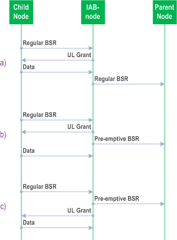
The IAB-node can reduce UL scheduling latency through signalling of a Pre-emptive BSR to its parent node. The IAB-node can send the Pre-emptive BSR based on UL grants it has provided to child nodes and/or UEs, or based on BSRs it has received from child nodes or UEs (Figure 4.7.3.3-1). The Pre-emptive BSR conveys the data expected rather than the data buffered.
4.7.4 Signalling procedures p. 34
4.7.4.1 IAB-node Integration p. 34
The IAB-node integration procedure is captured in TS 38.401.
4.7.4.2 IAB-node Migration p. 35
The IAB-node can migrate to a different parent node underneath the same IAB-donor-CU. The IAB-node continues providing access and backhaul service when migrating to a different parent node.
The IAB-MT can also migrate to a different parent node underneath another IAB-donor-CU. In this case, the collocated IAB-DU and the IAB-DU(s) of its descendant node(s) retain F1 connectivity with the initial IAB-donor-CU. The IAB-MT of each descendant node and all the served UEs retain the RRC connectivity with the initial IAB-donor-CU. This migration is referred to as inter-donor partial migration. The IAB-node, whose IAB-MT migrates to the new IAB-donor-CU, is referred to as a boundary IAB-node. After inter-donor partial migration, the F1 traffic of the IAB-DU and its descendant nodes is routed via the BAP layer of the IAB topology to which the IAB-MT has migrated.
Inter-donor partial migration is only supported for SA-mode.
The intra-donor IAB-node migration procedure and inter-donor partial migration procedures are captured in TS 38.401.
4.7.4.3 Topological Redundancy p. 35
The IAB-node may have redundant routes to the IAB-donor-CU(s).
For IAB-nodes operating in SA-mode, NR DC can be used to enable route redundancy in the BH by allowing the IAB-MT to have concurrent BH links with two parent nodes. The parent nodes may be connected to the same or to different IAB-donor-CUs, which control the establishment and release of redundant routes via these two parent nodes. Either parent node's gNB-DU functionality together with the respective IAB-donor-CU assumes the role of the IAB-MT's master node or secondary node. The NR DC framework (e.g., MCG/SCG-related procedures) is used to configure the dual radio links with the parent nodes (TS 37.340).
The procedure for establishment of topological redundancy for IAB-nodes operating in SA-mode is captured in TS 38.401.
An IAB-node operating in NR-DC may also use one of its links for BH connectivity with an IAB-donor and the other link for access-only connectivity with a separate gNB that does not assume IAB-donor role. The IAB-donor can assume the MN or the SN role. The IAB-node may exchange F1-C traffic with the IAB-donor via the backhaul link and/or via the access link with the gNB. In the latter case, the F1-C messages are carried over NR RRC between the IAB-node and the gNB, and via XnAP between the gNB and the IAB-donor.
IAB-nodes operating in EN-DC can exchange F1-C traffic with the IAB-donor via the MeNB. The F1-C message is carried over LTE RRC using SRB2 between IAB-node and MeNB and via X2AP between the MeNB and the IAB-donor.
The procedures for establishment of redundant transport of F1-C for IAB-nodes using NR-DC and EN-DC are captured in TS 37.340 and TS 38.401.
4.7.4.4 Backhaul RLF Recovery p. 35
When the IAB-node using SA-mode declares RLF on the backhaul link, it can perform RLF recovery at another parent node underneath the same or underneath a different IAB-donor-CU. In the latter case, the collocated IAB-DU and the IAB-DU(s) of its descendant node(s) may retain the F1 connectivity with the initial IAB-donor-CU, while the IAB-MT(s) of the descendant node(s) and all the served UEs retain the RRC connectivity with the initial IAB-donor-CU, in the same manner as for inter-donor partial migration.
The BH RLF recovery procedure for the IAB-node is captured in TS 38.401. BH RLF declaration for IAB-node and the aspects of RLF recovery by the IAB-MT are handled in clause 9.2.7 of the present document.
4.7.4.5 OTA timing synchronization p. 35
An IAB-DU is subject to the same downlink timing alignment of a gNB. The IAB-DU may use the received downlink signal from a parent as a reference to control its downlink timing using TA in conjunction with an additional Tdelta parameter received by the collocated IAB-MT from the parent via MAC-CE.
4.7.4.6 Inter node discovery p. 36
Inter node discovery is supported via SSB-based and/or CSI-RS-based measurements. An IAB-node can be configured to transmit and receive off synchronization raster SSB signals to discover neighbouring IAB-nodes. The configuration is not expected to create a conflict between IAB-DU SSB transmission and IAB-MT SSB measurement windows.
4.7.5 Mobile IAB |R18| p. 36
4.7.5.1 General p. 36
Mobile IAB introduces the mobile IAB-node, which is a RAN node that provides NR access links to UEs and an NR backhaul link to a parent node, and that can conduct physical mobility across the RAN area. The mobile IAB-node includes a mobile IAB-MT and a mobile IAB-DU. Mobile IAB supports the same functionality as IAB unless explicitly specified. The following enhancements/restrictions only apply to mobile IAB:
- The mobile IAB-node uses the mobile IAB-node authorization procedure defined in TS 38.401 and the MBSR authorization procedure defined in TS 23.501.
- A RAN node operating as a mobile IAB-node shall not concurrently operate as an IAB-node. During network integration, the RAN node shall indicate whether it intends to operate as a mobile IAB-node or as an IAB-node via an indicator in the RRCSetupComplete message.
- The parent node indicates support for mobile IAB-nodes by broadcasting a mobile-IAB-specific indicator in SIB1.
- The mobile IAB-node shall not have descendent nodes. A mobile-IAB cell shall therefore not broadcast any indication that it is a suitable parent node for IAB-nodes or mobile IAB-nodes.
- The cell of a mobile IAB-DU may indicate to UEs via a SIB1 indicator that it is a mobile-IAB cell.
- The mobile IAB-node uses the mobile IAB-node network integration procedure as defined in TS 38.401.
- The mobile IAB-MT can perform the mobile IAB-MT migration procedures via Xn handover and/or via NG handover as defined in TS 38.401. The mobile IAB-MT can also perform the mobile IAB-node recovery procedure as defined in TS 38.401.
- The mobile IAB-node can perform the mobile IAB-DU migration procedure, where a new logical mobile IAB-DU is established on the mobile IAB-node and the initial logical mobile IAB-DU is released some time later. The UE identifies the cells of the two logical mobile IAB-DUs as different physical cells. During this procedure, the UEs connected via the mobile IAB-node are handed over from the initial logical mobile IAB-DU, referred to as the source logical mobile IAB-DU, to the new logical mobile IAB-DU, referred to as the target logical mobile IAB-DU. The details of this procedure are defined in TS 38.401. Enhancements related to BAP for mobile IAB-DU migration are defined in TS 38.340.
- When a RAN node is operating as a mobile IAB node, dual connectivity for this node is not supported.
4.7.5.2 Void
4.8 Non-Public Networks |R16| p. 36
A Non-Public Network (NPN) is a network for non-public use (see TS 22.261), which can be deployed as (see TS 23.501):
- a Stand-alone Non-Public Network (SNPN) when not relying on network functions provided by a PLMN; or
- a Public Network Integrated (PNI) NPN when relying on the support of a PLMN.
4.9 Network-Controlled Repeaters |R18| p. 37
4.9.1 Architecture p. 37
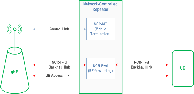
A Network-Controlled Repeater node, referred to as NCR-node, is an RF repeater that enables wireless amplifying-and-forwarding functionality in NG-RAN. The NCR-node is capable of receiving and applying side control information from a gNB with additional functionality to support Network-Controlled Repeater.
The NCR-node comprises an NCR-MT and an NCR-Fwd. The NCR-MT is an entity supporting a subset of the UE functionality that communicates with the gNB to receive side control information via a control link based on the NR Uu interface. The NCR-Fwd is the function performing amplifying-and-forwarding of signals between gNB and UE via the NCR-Fwd backhaul link and NCR-Fwd access link, respectively. The NCR-Fwd can support multiple beams towards the UE. The NCR-Fwd can support multiple beams in the backhaul link, and those may be different from the beams in the control link. The behaviour of the NCR-Fwd is controlled according to the side control information received from the gNB. The NCR-node is modelled as depicted in Figure 4.9.1-1.
An NCR-MT establishes SRBs and, optionally, DRB(s) with a gNB. The establishment of DRB(s) can be used to transport OAM traffic.
The signal that NCR-Fwd forwards is associated to the cell that the NCR-MT is connected to via the control link. Whether the NCR-Fwd can forward other signals is up to implementation.
4.9.2 Capabilities p. 37
Carrier Aggregation (CA), Multi-Radio Dual Connectivity (MR-DC), handover and its related features (e.g., CHO, DAPS, CPAC, etc.) are not supported by NCR-MT, as defined together with other limitations in TS 38.306.
4.9.3 Signalling procedures p. 37
RRC signalling is utilized to configure the NCR-MT to receive side control information from a gNB, which is used by the NCR-Fwd to determine whether and how to amplify-and-forward RF signals. If the side control configuration is removed, the NCR-Fwd ceases its amplifying-and-forwarding function.
MAC CE indications can be used to configure the backhaul link and the access link of the NCR-Fwd as specified in TS 38.321.
When the NCR-MT is in RRC_CONNECTED state, the NCR-Fwd may amplify-and-forward RF signals based on the side control information received from the gNB. The NCR-MT does not support RRM measurements in RRC_CONNECTED.
When the NCR-MT transitions from RRC_CONNECTED state to RRC_INACTIVE state, the NCR-Fwd may continue to amplify-and-forward RF signals in accordance with the last side control information received from the gNB. When the NCR-MT is in RRC_INACTIVE state, the NCR-Fwd ceases to amplify-and-forward RF signals if no suitable cell is detected, or if the NCR-MT selects a different cell than the last serving cell on which side control configuration was received.
When an NCR-MT in RRC_INACTIVE state determines degradation of the NCR-Fwd backhaul link beam, then the NCR-Fwd should cease amplifying-and-forwarding RF signals, and the NCR-MT should attempt to resume its RRC connection (with cause value mo-Signalling). The criteria to evaluate backhaul beam degradation are left to the NCR-node implementation.
When the NCR-MT transitions from RRC_CONNECTED state to RRC_IDLE, the NCR-Fwd ceases any amplifying-and-forwarding of RF signals. How an NCR-MT transitions back from RRC_IDLE state to RRC_CONNECTED state is left to NCR-node or network implementation.
An NCR-MT can detect RLF on the control link as specified in clause 5.3.10 of TS 38.331. When RLF is detected, the NCR-MT performs the RRC re-establishment procedure as specified in TS 38.331. During the RRC re-establishment procedure, the NCR-Fwd ceases to amplify-and-forward RF signals.
After successfully performing the RRC re-establishment procedure, the NCR-MT waits for the new side control configuration for the NCR-Fwd to resume the amplifying-and-forwarding of RF signals.
An NCR-MT can also perform Beam Failure Detection (BFD) and Beam Failure Recovery (BFR) as described in clause 9.2.8. Once the NCR-MT detects beam failure in the control link, the NCR-Fwd should cease amplifying-and-forwarding RF signals until BFR is completed.
4.9.4 OAM aspects p. 38
The transport connection between the NCR-node and its OAM may be provided by the NCR-MT's PDU session. A Network-Controlled Repeater may be configured with a list of allowed gNB cell(s) that the NCR-MT is allowed to connect with, and/or a list of forbidden gNB cell(s) that the NCR-MT is not allowed to connect with.
The information on the physical beam(s) used by NCR-Fwd for access link may be provided by OAM to the gNB and the Network-Controlled Repeater for operation. How to characterize and provide the physical beams of NCR-Fwd is up to implementation.
4.9.5 Network-controlled repeater management p. 38
Network-Controlled Repeater identification is performed in RAN, and Network-Control Repeater authorization is performed in 5GC. The general procedure of the Network-Controlled Repeater management is illustrated in Figure 4.9.5-1:
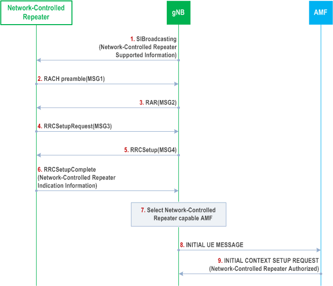
Step 1.
Other steps refer to the signalling flow as defined in clause 9.2.1.3.
The gNB broadcasts the Network-Controlled Repeater supported information via system information.
Step 6.
When a Network-Controlled Repeater is trying to access the network as a Network-Controlled Repeater, the Network-Controlled Repeater indication is sent to the serving gNB.
Step 7.
The serving gNB selects an appropriate AMF for the Network-Controlled Repeater.
Step 9.
AMF provides Network-Controlled Repeater authorization information to the gNB.