Content for TS 38.300 Word version: 18.4.0
1…
4…
4.7…
5…
5.3…
5.4…
6…
6.2…
6.6…
7…
8…
9…
9.2.2…
9.2.2.5…
9.2.3…
9.2.3.2…
9.2.3.3…
9.2.4…
9.2.6…
9.3…
10…
11…
15…
15.5…
16…
16.2…
16.3…
16.4…
16.8…
16.9…
16.10…
16.12…
16.12.5…
16.12.6…
16.12.6.3
16.12.7
16.13…
16.14…
16.15…
16.18…
16.19…
16.21…
16.21.3…
17…
18…
19
20…
21…
A…
B…
C…
G…
9.2.3.3 Re-establishment procedure
9.2.3.4 Conditional Handover
9.2.3.4.1 General
9.2.3.4.2 C-plane handling
9.2.3.4.3 U-plane handling
9.2.3.4.4 Data Forwarding
9.2.3.5 L1/L2 Triggered Mobility
9.2.3.5.1 General
9.2.3.5.2 C-Plane Handling
9.2.3.5.3 U-Plane Handling
9.2.3.6 RACH-less handover
...
...
9.2.3.3 Re-establishment procedure p. 96
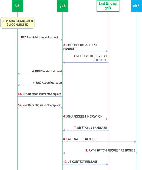
A UE in RRC_CONNECTED may initiate the re-establishment procedure to continue the RRC connection when a failure condition occurs (e.g. radio link failure, reconfiguration failure, integrity check failure…).
The following Figure describes the re-establishment procedure started by the UE:

Step 1.
The IAB-MT in SA mode follows the same re-establishment procedure as described for the UE. After the backhaul has been established, the re-establishment procedure of the IAB-MT is part of the intra-CU backhaul RLF recovery procedure for IAB-nodes defined in TS 38.401. Modifications to the configuration of BAP sublayer and higher protocol layers above the BAP sublayer are described in TS 38.401.
The UE re-establishes the connection, providing the UE Identity (PCI+C-RNTI) to the gNB where the trigger for the re-establishment occurred.
Step 2.
If the UE Context is not locally available, the gNB, requests the last serving gNB to provide UE Context data.
Step 3.
The last serving gNB provides UE context data.
Step 4/4a.
The gNB continues the re-establishment of the RRC connection. The message is sent on SRB1.
Step 5/5a.
The gNB may perform the reconfiguration to re-establish SRB2 and DRBs when the re-establishment procedure is ongoing.
Step 6/7.
If loss of user data buffered in the last serving gNB shall be prevented, the gNB provides forwarding addresses, and the last serving gNB provides the SN status to the gNB.
Step 8/9.
The gNB performs path switch.
Step 10.
The gNB triggers the release of the UE resources at the last serving gNB.
9.2.3.4 Conditional Handover |R16| p. 97
9.2.3.4.1 General p. 97
A Conditional Handover (CHO) is defined as a handover that is executed by the UE when one or more handover execution conditions are met. The UE starts evaluating the execution condition(s) upon receiving the CHO configuration, and stops evaluating the execution condition(s) once a handover is executed.
The following principles apply to CHO:
- The CHO configuration contains the configuration of CHO candidate cell(s) generated by the candidate gNB(s) and execution condition(s) generated by the source gNB.
- An execution condition may consist of one or two trigger condition(s) (CHO events A3/A5, as defined in TS 38.331). Only single RS type is supported and at most two different trigger quantities (e.g. RSRP and RSRQ, RSRP and SINR, etc.) can be configured simultaneously for the evalution of CHO execution condition of a single candidate cell.
- Before any CHO execution condition is satisfied, upon reception of HO command (without CHO configuration) or LTM cell switch command MAC CE, the UE executes the HO procedure as described in clause 9.2.3.2 or LTM cell switch procedure as described in clause 9.2.3.5, regardless of any previously received CHO configuration.
- While executing CHO, i.e. from the time when the UE starts synchronization with target cell, UE does not monitor source cell.
9.2.3.4.2 C-plane handling p. 97
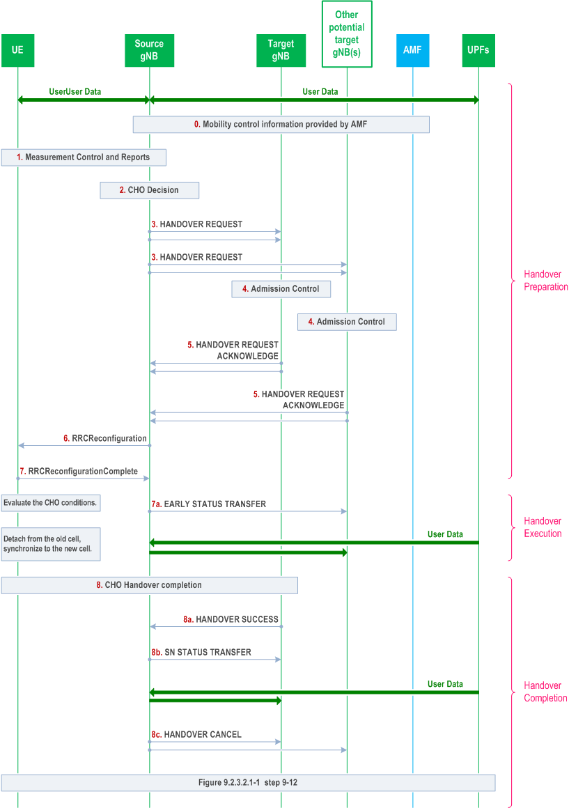
As in intra-NR RAN handover, in intra-NR RAN CHO, the preparation and execution phase of the conditional handover procedure is performed without involvement of the 5GC; i.e. preparation messages are directly exchanged between gNBs. The release of the resources at the source gNB during the conditional handover completion phase is triggered by the target gNB. The Figure below depicts the basic conditional handover scenario where neither the AMF nor the UPF changes:

Step 0/1.
Same as step 0, 1 in Figure 9.2.3.2.1-1 of clause 9.2.3.2.1.
Step 2.
The source gNB decides to use CHO.
Step 3.
The source gNB requests CHO for one or more candidate cells belonging to one or more candidate gNBs. A CHO request message is sent for each candidate cell.
Step 4.
Same as step 4 in Figure 9.2.3.2.1-1 of clause 9.2.3.2.1.
Step 5.
The candidate gNB(s) sends CHO response (HO REQUEST ACKNOWLEDGE) including configuration of CHO candidate cell(s) to the source gNB. The CHO response message is sent for each candidate cell.
Step 6.
The source gNB sends an RRCReconfiguration message to the UE, containing the configuration of CHO candidate cell(s) and CHO execution condition(s).
Step 7.
The UE sends an RRCReconfigurationComplete message to the source gNB.
Step 7a.
If early data forwarding is applied, the source gNB sends the EARLY STATUS TRANSFER message.
Step 8.
The UE maintains connection with the source gNB after receiving CHO configuration, and starts evaluating the CHO execution conditions for the candidate cell(s). If at least one CHO candidate cell satisfies the corresponding CHO execution condition, the UE detaches from the source gNB, applies the stored corresponding configuration for that selected candidate cell, synchronises to that candidate cell and completes the RRC handover procedure by sending RRCReconfigurationComplete message to the target gNB. The UE releases stored CHO configurations after successful completion of RRC handover procedure.
Step 8a/b.
The target gNB sends the HANDOVER SUCCESS message to the source gNB to inform that the UE has successfully accessed the target cell. In return, the source gNB sends the SN STATUS TRANSFER message following the principles described in step 7 of Intra-AMF/UPF Handover in clause 9.2.3.2.1.
Step 8c.
The source gNB sends the HANDOVER CANCEL message toward the other signalling connections or other candidate target gNBs, if any, to cancel CHO for the UE.
9.2.3.4.3 U-plane handling p. 99
The U-plane handling for Conditional Handover follows the same principles for DAPS handover in clause 9.2.3.2.2, if early data forwarding is applied, except that, in case of Full Configuration, HFN and PDCP SN are reset in the target gNB after the SN assignment is handed over to the target gNB. If late data forwarding is applied, the U-plane handling follows the RLC-AM or RLC-UM bearer principles defined in clause 9.2.3.2.2.
9.2.3.4.4 Data Forwarding p. 99
If late data forwarding is applied, the source NG-RAN node initiates data forwarding once it knows which target NG-RAN node the UE has successfully accessed. In that case the behavior of the Conditional Handover data forwarding follows the same behavior as defined in clause 9.2.3.2.3 for the intra-system handover data forwarding, except the behavior for DRBs configured with DAPS handover.
If early data forwarding is applied instead, the source NG-RAN node initiates data forwarding before the UE executes the handover, to a candidate target node of interest. The behavior of early data forwarding for the Conditional Handover follows the same principles for DRBs configured with DAPS handover in the intra-system handover as defined in clause 9.2.3.2.3.
9.2.3.5 L1/L2 Triggered Mobility |R18| p. 99
9.2.3.5.1 General p. 99
LTM is a procedure in which a gNB receives L1 or L3 measurement report(s) from a UE, and on their basis the gNB may change UE serving cell by a cell switch command signalled via a MAC CE. The cell switch command indicates an LTM candidate configuration that the gNB previously prepared and provided to the UE through RRC signalling. Then the UE switches to the target configuration according to the cell switch command. The LTM procedure can be used to reduce the mobility latency as described in Annex G.
When configured by the network, it is possible to activate TCI states of one or multiple cells that are different from the current serving cell. For instance, the TCI states of the LTM candidate cells can be activated in advance before any of those cells become the serving cell. This allows the UE to be DL synchronized with those cells, thereby facilitating a faster cell switch to one of those cells when cell switch is triggered. All the activated TCI states except those received in the cell switch command are deactivated upon LTM cell switch execution.
When configured by the network, it is possible to initiate UL TA acquisition (called early TA) procedure of one or multiple cells that are different from the current serving cells. If the cell has the same NTA as the current serving cells or NTA=0, early TA acquisition procedure is not required. The network may request the UE to perform early TA acquisition of a candidate cell before a cell switch. The early TA acquisition procedure is triggered by PDCCH order as specified in clause 9.2.6 or realized through UE-based TA measurement as configured by RRC. In the former case, the gNB/gNB-DU to which the candidate cell belongs calculates the TA value and sends it to the gNB/gNB-DU to which the serving cell belongs via gNB-CU. The serving cell sends the TA value in the LTM cell switch command MAC CE when triggering LTM cell switch. In the latter case, the UE performs TA measurement for the candidate cells after being configured by RRC but the exact time the UE performs TA measurement is up to UE implementation. The UE applies the TA value measured by itself and performs RACH-less LTM upon receiving the cell switch command, if it does not include any valid TA value. The network may also send a TA value in the LTM cell switch command MAC CE without early TA acquisition.
When two TAG IDs are configured for an LTM candidate cell, the gNB-DU to which the LTM candidate cell belongs assigns the same TAG ID pointer value for each TRP to be used by the UEs.
Depending on the availability of a valid TA value, the UE performs either a RACH-less LTM or RACH-based LTM cell switch. If the valid TA value is provided in the cell switch command, the UE applies the TA value as instructed by the network. In the case where UE-based TA measurement is configured, but no valid TA value is provided in the cell switch command, the UE applies the valid TA value by itself if available. The UE performs RACH-less LTM cell switch upon receiving the cell switch command whenever a valid TA value is available. If no valid TA value is available, the UE performs RACH-based LTM cell switch.
Regardless of whether the UE is configured for UE-based TA measurement for a certain candidate cell, it will still follow the PDCCH order, which includes performing a random access procedure towards one or more candidate cells. This also applies to the candidate cells for which the UE is capable of deriving TA values by itself. Additionally, regardless of whether the UE has already performed a random access procedure towards the candidate cells, it will still follow the UE-based measurement configuration if configured by the network.
For RACH-less LTM, the UE accesses the target cell using either a configured grant or a dynamic grant. The configured grant is provided in the LTM candidate configuration, and the UE selects the configured grant occasion associated with the beam indicated in the cell switch command. Upon initiation of LTM cell switch to the target cell, the UE starts to monitor PDCCH on the target cell for dynamic scheduling. Before RACH-less LTM procedure completion, the UE shall not trigger random access procedure if it does not have a valid PUCCH resource for triggered SRs.
The following principles apply to LTM:
- Security keys are maintained upon an LTM cell switch;
- Subsequent LTM is supported.
- PCell change in non-CA scenario and non-DC scenario;
- PCell and SCell(s) change in CA scenario;
- Dual connectivity scenario: including PCell and MCG SCell(s) change and intra-SN PSCell and SCG SCell(s) change without MN involvement. LTM for simultaneous PCell and PSCell change is not supported.
9.2.3.5.2 C-Plane Handling p. 100
Cell switch command is conveyed in a MAC CE, which contains the necessary information to perform the LTM cell switch.
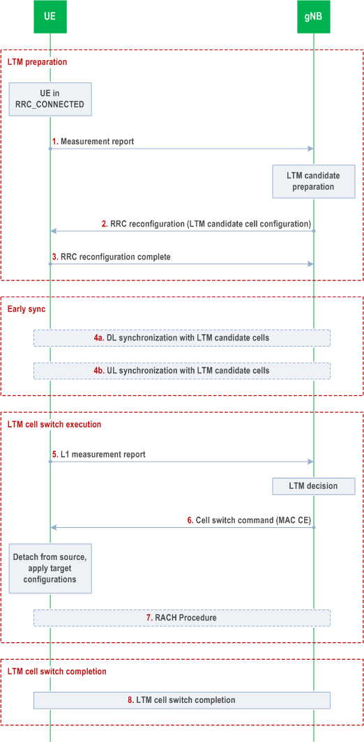
The overall procedure for LTM is shown in Figure 9.2.3.5.2-1 below. Subsequent LTM is done by repeating the early synchronization, LTM cell switch execution, and LTM cell switch completion steps without the need to release, reconfigure or add other LTM candidate configurations after each LTM cell switch completion. The general procedure over the air interface is applicable to SCG LTM. Further details of SCG LTM can be found in TS 37.340.

The procedure for LTM is as follows:
Step 1.
The steps 4-8 can be performed multiple times for subsequent LTM cell switch executions using the LTM candidate configuration(s) provided in step 2.
The procedure over the air interface described in Figure 9.2.3.5.2-1 is applicable to both intra-gNB-DU LTM and inter-gNB-DU LTM. The overall LTM procedures over F1-C interface are captured in TS 38.401.
The UE sends a MeasurementReport message to the gNB. The gNB decides to configure LTM and initiates LTM preparation.
Step 2.
The gNB transmits an RRCReconfiguration message to the UE including the LTM candidate configurations.
Step 3.
The UE stores the LTM candidate configurations and transmits an RRCReconfigurationComplete message to the gNB.
Step 4a.
The UE performs DL synchronization with the LTM candidate cell(s) before receiving the cell switch command. The UE may activate and deactivate TCI states of LTM candidate cell(s), as triggered by the gNB and defined in TS 38.133.
Step 4b.
The UE may perform UL synchronization with LTM candidate cell(s) before receiving the cell switch command, by using UE-based TA measurement, if configured, and/or by transmitting a preamble towards the candidate cell, as triggered by the gNB. When UE-based TA measurement is configured, UE acquires the TA value(s) of the candidate cell(s) by measurement. UE performs early TA acquisition with the candidate cell(s) as requested by the network before receiving the cell switch command as specified in clause 9.2.6 and TS 38.133. This is done via CFRA triggered by a PDCCH order from the source cell, following which the UE sends preamble towards the indicated candidate cell. In order to minimize the data interruption of the source cell due to CFRA towards the candidate cell(s), the UE does not receive random access response from the network for the purpose of TA value acquisition and the TA value of the candidate cell is indicated in the cell switch command. The UE does not maintain the TA timer for the candidate cell and relies on network implementation to guarantee the TA validity.
Step 5.
The UE performs L1 measurements on the configured LTM candidate cell(s) and transmits L1 measurement reports to the gNB. L1 measurement should be performed as long as RRC reconfiguration (step 2) is applicable. The UE can also perform L3 measurement reporting to the gNB, including beam level measurement results on cell(s) which are configured as LTM candidate cell(s) according to the received network configuration.
Step 6.
The gNB decides to execute cell switch to a target cell and transmits an LTM cell switch command MAC CE triggering cell switch by including a target configuration ID which indicates the index of the candidate configuration of the target cell, a beam indicated with a TCI state or beams indicated with DL and UL TCI states, and a timing advance command for the target cell, if available. The UE switches to the target cell and applies the candidate configuration indicated by the target configuration ID.
Step 7.
The UE performs the random access procedure towards the target cell, if UE does not have valid TA of the target cell as specified in clause 5.18.35 of TS 38.321.
Step 8.
The UE completes the LTM cell switch procedure by sending RRCReconfigurationComplete message to target cell. If the UE has performed a RA procedure in step 7 the UE considers that LTM cell switch execution is successfully completed when the random access procedure is successfully completed. For RACH-less LTM, the UE considers that LTM cell switch execution is successfully completed when the UE determines that the network has successfully received its first UL data.
9.2.3.5.3 U-Plane Handling p. 102
After receiving an LTM cell switch command MAC CE, the UE performs MAC reset. Whether the UE performs RLC re-establishment and PDCP data recovery during cell switch is explicitly controlled by the network through RRC signalling.
9.2.3.6 RACH-less handover |R18| p. 102
During intra-gNB HO procedure, RACH-less handover can be configured for a UE. The RACH-less handover procedure applies the following functionality:
- The UE uses the same timing advance value (i.e., NTA value) at the target cell as in the source cell or timing advance value (i.e., NTA value) of 0.
- The handover command for the UE may contain a beam identifier for the beam to be used by the UE at the target cell. The beam may be determined based on a UE measurement report and/or left up to gNB implementation, e.g., using the target cell's knowledge about the beam(s) used by the UE at the co-located source cell.
- The handover command may include a configured UL grant. UE can fallback to RACH when there is no valid configured uplink grant. Alternatively, an UL grant is dynamically signalled by the target cell.
- The UE transmits the RRCReconfigurationComplete message using the configured or dynamically signalled UL grant. Successful UL data reception on the target cell terminates the RACH-less handover execution.