Content for TS 38.300 Word version: 18.4.0
1…
4…
4.7…
5…
5.3…
5.4…
6…
6.2…
6.6…
7…
8…
9…
9.2.2…
9.2.2.5…
9.2.3…
9.2.3.2…
9.2.3.3…
9.2.4…
9.2.6…
9.3…
10…
11…
15…
15.5…
16…
16.2…
16.3…
16.4…
16.8…
16.9…
16.10…
16.12…
16.12.5…
16.12.6…
16.12.6.3
16.12.7
16.13…
16.14…
16.15…
16.18…
16.19…
16.21…
16.21.3…
17…
18…
19
20…
21…
A…
B…
C…
G…
5 Physical Layer
5.1 Waveform, numerology and frame structure
5.2 Downlink
5.2.1 Downlink transmission scheme
5.2.2 Physical-layer processing for physical downlink shared channel
5.2.3 Physical downlink control channels
5.2.4 Synchronization signal and PBCH block
5.2.5 Physical layer procedures
5.2.5.1 Link adaptation
5.2.5.2 Power Control
5.2.5.3 Cell search
5.2.5.4 HARQ
5.2.5.5 Reception of SIB1
5.2.6 Downlink Reference Signals and Measurements for Positioning
...
...
5 Physical Layer p. 39
5.1 Waveform, numerology and frame structure p. 39
The downlink transmission waveform is conventional OFDM using a Cyclic Prefix. The uplink transmission waveform is conventional OFDM using a CP with a transform precoding function performing DFT spreading that can be disabled or enabled. For operation with shared spectrum channel access in FR1, the uplink transmission waveform subcarrier mapping can map to subcarriers in one or more PRB interlaces.

The numerology is based on exponentially scalable sub-carrier spacing Δf = 2µ × 15 kHz with μ={0,1,3,4,5,6} for PSS, SSS and PBCH and μ={0,1,2,3,5,6} for other channels. Normal CP is supported for all sub-carrier spacings, Extended CP is supported for μ=2. 12 consecutive sub-carriers form a Physical Resource Block (PRB). Up to 275 PRBs are supported on a carrier.
| µ | Δf = 2µ × 15 [kHz] | CP | Supported for data | Supported for synch |
|---|---|---|---|---|
| 0 | 15 | Normal | Yes | Yes |
| 1 | 30 | Normal | Yes | Yes |
| 2 | 60 | Normal, Extended | Yes | No |
| 3 | 120 | Normal | Yes | Yes |
| 4 | 240 | Normal | No | Yes |
| 5 | 480 | Normal | Yes | Yes |
| 6 | 960 | Normal | Yes | Yes |
The UE may be configured with one or more bandwidth parts on a given component carrier, of which only one can be active at a time, as described in clauses 7.8 and 6.10 respectively. The active bandwidth part defines the UE's operating bandwidth within the cell's operating bandwidth. For initial access, and until the UE's configuration in a cell is received, initial bandwidth part detected from system information is used.
Downlink and uplink transmissions are organized into frames with 10 ms duration, consisting of ten 1 ms subframes. Each frame is divided into two equally-sized half-frames of five subframes each. The slot duration is 14 symbols with Normal CP and 12 symbols with Extended CP, and scales in time as a function of the used sub-carrier spacing so that there is always an integer number of slots in a subframe.
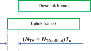
Timing Advance TA is used to adjust the uplink frame timing relative to the downlink frame timing.

Operation on both paired and unpaired spectrum is supported.
5.2 Downlink p. 40
5.2.1 Downlink transmission scheme p. 40
Demodulation Reference Signal (DMRS) based spatial multiplexing is supported for Physical Downlink Shared Channel (PDSCH). Up to 8, 12, 16 and 24 orthogonal DL DMRS ports are supported for type 1, type 2, enhanced type 1, and enhanced type 2 DMRS respectively. Up to 8 orthogonal DL DMRS ports per UE are supported for SU-MIMO and up to 4 orthogonal DL DMRS ports per UE are supported for MU-MIMO. The number of SU-MIMO code words is one for 1-4 layer transmissions and two for 5-8 layer transmissions.
The DMRS and corresponding PDSCH are transmitted using the same precoding matrix and the UE does not need to know the precoding matrix to demodulate the transmission. The transmitter may use different precoder matrix for different parts of the transmission bandwidth, resulting in frequency selective precoding. The UE may also assume that the same precoding matrix is used across a set of Physical Resource Blocks (PRBs) denoted Precoding Resource Block Group (PRG).
Transmission durations from 2 to 14 symbols in a slot is supported.
Aggregation of multiple slots with Transport Block (TB) repetition is supported.
5.2.2 Physical-layer processing for physical downlink shared channel p. 40
The downlink physical-layer processing of transport channels consists of the following steps:
- Transport block CRC attachment;
- Code block segmentation and code block CRC attachment;
- Channel coding: LDPC coding;
- Physical-layer hybrid-ARQ processing;
- Rate matching;
- Scrambling;
- Modulation: QPSK, 16QAM, 64QAM, 256QAM, and 1024QAM;
- Layer mapping;
- Mapping to assigned resources and antenna ports.
5.2.3 Physical downlink control channels p. 41
The Physical Downlink Control Channel (PDCCH) can be used to schedule DL transmissions on PDSCH and UL transmissions on PUSCH, where the Downlink Control Information (DCI) on PDCCH includes:
- Downlink assignments containing at least modulation and coding format, resource allocation, and hybrid-ARQ information related to DL-SCH;
- Uplink scheduling grants containing at least modulation and coding format, resource allocation, and hybrid-ARQ information related to UL-SCH.
- Activation and deactivation of configured PUSCH transmission with configured grant;
- Activation and deactivation of PDSCH semi-persistent transmission;
- Notifying one or more UEs of the slot format;
- Notifying one or more UEs of the PRB(s) and OFDM symbol(s) where the UE may assume no transmission is intended for the UE;
- Transmission of TPC commands for PUCCH and PUSCH;
- Transmission of one or more TPC commands for SRS transmissions by one or more UEs;
- Switching a UE's active bandwidth part;
- Initiating a random access procedure;
- Indicating the UE(s) to monitor the PDCCH during the next occurrence of the DRX on-duration;
- In IAB context, indicating the availability for soft symbols of an IAB-DU;
- Triggering one shot HARQ-ACK codebook feedback;
-
For operation with shared spectrum channel access:
- Triggering search space set group switching;
- Indicating one or more UEs about the available RB sets and channel occupancy time duration;
- Indicating downlink feedback information for configured grant PUSCH (CG-DFI).
5.2.4 Synchronization signal and PBCH block p. 42
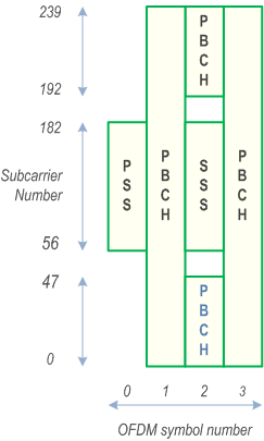
The Synchronization Signal and PBCH block (SSB) consists of primary and secondary synchronization signals (PSS, SSS), each occupying 1 symbol and 127 subcarriers, and PBCH spanning across 3 OFDM symbols and 240 subcarriers, but on one symbol leaving an unused part in the middle for SSS as show in Figure 5.2.4-1. For the 3 MHz channel bandwidth, the PBCH is further equally punctured from both edges to span 144 subcarriers. The possible time locations of SSBs within a half-frame are determined by sub-carrier spacing and the periodicity of the half-frames where SSBs are transmitted is configured by the network. During a half-frame, different SSBs may be transmitted in different spatial directions (i.e. using different beams, spanning the coverage area of a cell).
Within the frequency span of a carrier, multiple SSBs can be transmitted. The PCIs of SSBs transmitted in different frequency locations do not have to be unique, i.e. different SSBs in the frequency domain can have different PCIs. However, when an SSB is associated with an RMSI, the SSB is referred to as a Cell-Defining SSB (CD-SSB). A PCell is always associated to a CD-SSB located on the synchronization raster.
When an SSB is not associated with an RMSI, the SSB is referred to as a non-Cell Defining SSB (NCD-SSB), which can be used to perform RLM, BFD, and RRM measurements and measurements for RA resource selection inside the active DL BWP when the active BWP does not contain the CD-SSB. A UE may be configured with multiple SSBs provided that each BWP is configured with at most one SSB (CD-SSB or NCD-SSB).

Polar coding is used for PBCH.
The UE may assume a band-specific sub-carrier spacing for the SSB unless a network has configured the UE to assume a different sub-carrier spacing.
PBCH symbols carry its own frequency-multiplexed DMRS.
QPSK modulation is used for PBCH.
The PBCH physical layer model is described in TS 38.202.
5.2.5 Physical layer procedures p. 43
5.2.5.1 Link adaptation p. 43
Link adaptation (AMC: adaptive modulation and coding) with various modulation schemes and channel coding rates is applied to the PDSCH. The same coding and modulation is applied to all groups of resource blocks belonging to the same L2 PDU scheduled to one user within one transmission duration and within a MIMO codeword.
For channel state estimation purposes, the UE may be configured to measure CSI-RS and estimate the downlink channel state based on the CSI-RS measurements. The UE feeds the estimated channel state back to the gNB to be used in link adaptation.
5.2.5.2 Power Control p. 43
Downlink power control can be used.
5.2.5.3 Cell search p. 43
Cell search is the procedure by which a UE acquires time and frequency synchronization with a cell and detects the Cell ID of that cell. NR cell search is based on the primary and secondary synchronization signals, and PBCH DMRS, located on the synchronization raster.
5.2.5.4 HARQ p. 44
Asynchronous Incremental Redundancy Hybrid ARQ is supported. The gNB provides the UE with the HARQ-ACK feedback timing either dynamically in the DCI or semi-statically in an RRC configuration. Retransmission of HARQ-ACK feedback is supported by using enhanced dynamic codebook and/or one-shot triggering of HARQ-ACK transmission for (i) all configured CCs and HARQ processes in the PUCCH group, (ii) a configured subset of CCs and/or HARQ processes in the PUCCH group, or (iii) a dynamically indicated HARQ-ACK feedback instance. For HARQ-ACK of SPS PDSCH without associated PDCCH, in case of HARQ-ACK dropping due to TDD specific collisions, the HARQ-ACK feedback can be deferred to a next available PUCCH transmission occasion.
The UE may be configured to receive code block group based transmissions where retransmissions may be scheduled to carry a sub-set of all the code blocks of a TB.
5.2.5.5 Reception of SIB1 p. 44
The Master Information Block (MIB) on PBCH provides the UE with parameters (e.g. CORESET#0 configuration) for monitoring of PDCCH for scheduling PDSCH that carries the System Information Block 1 (SIB1). PBCH may also indicate that there is no associated SIB1, in which case the UE may be pointed to another frequency from where to search for an SSB that is associated with a SIB1 as well as a frequency range where the UE may assume no SSB associated with SIB1 is present. The indicated frequency range is confined within a contiguous spectrum allocation of the same operator in which SSB is detected.
5.2.6 Downlink Reference Signals and Measurements for Positioning |R16| p. 44
The DL Positioning Reference Signals (DL PRS) are defined to facilitate support of different positioning methods such as DL-TDOA, DL-AoD, multi-RTT through the following set of UE measurements DL RSTD, DL PRS-RSRP/DL PRS-RSRPP, and UE Rx-Tx time difference respectively as described in TS 38.305. The DL PRS also facilitates Carrier Phase Positioning measurements such as DL-RSCP and DL-RSCPD as described in TS 38.305.
Besides DL PRS signals, UE can use SSB and CSI-RS for RRM (RSRP and RSRQ) measurements for E-CID type of positioning.