Content for TS 38.300 Word version: 18.4.0
1…
4…
4.7…
5…
5.3…
5.4…
6…
6.2…
6.6…
7…
8…
9…
9.2.2…
9.2.2.5…
9.2.3…
9.2.3.2…
9.2.3.3…
9.2.4…
9.2.6…
9.3…
10…
11…
15…
15.5…
16…
16.2…
16.3…
16.4…
16.8…
16.9…
16.10…
16.12…
16.12.5…
16.12.6…
16.12.6.3
16.12.7
16.13…
16.14…
16.15…
16.18…
16.19…
16.21…
16.21.3…
17…
18…
19
20…
21…
A…
B…
C…
G…
16.9 Sidelink
16.9.1 General
16.9.2 Radio Protocol Architecture for NR sidelink communication
16.9.2.1 Overview
16.9.2.2 MAC
16.9.2.3 RLC
16.9.2.4 PDCP
16.9.2.5 SDAP
16.9.2.6 RRC
16.9.3 Radio Resource Allocation
16.9.3.1 General
16.9.3.2 Scheduled Resource Allocation
16.9.3.3 UE Autonomous Resource Selection
16.9.3.4 LTE and NR Sidelink co-channel coexistence
16.9.4 Uu Control
16.9.4.1 General
16.9.4.2 Control of connected UEs
16.9.4.3 Control of idle/inactive UEs
16.9.5 Sidelink Discovery
16.9.6 SL DRX
16.9.6.1 General
16.9.6.2 Unicast
16.9.6.3 Groupcast/Broadcast
16.9.6.4 Alignment between Uu DRX and SL DRX
16.9.7 Power Savings Resource Allocation
16.9.8 Inter-UE Coordination (IUC)
16.9.9 Sidelink in Shared Spectrum (SL-U)
16.9.9.1 Overview
16.9.9.2 Channel Access Priority Classes for Sidelink (SL-CAPC)
16.9.9.3 Sidelink Specific Consistent LBT Failure
16.9.9.4 COT Sharing
16.9.9.5 Resource Allocation
16.9.10 Sidelink CA
...
...
16.9 Sidelink |R16| p. 166
16.9.1 General p. 166
In this clause, an overview of NR sidelink communication and how NG-RAN supports NR sidelink communication, V2X sidelink communication and Ranging/Sidelink positioning is given. V2X sidelink communication is specified in TS 36.300. Ranging/Sidelink positioning is specified in TS 38.305.
The NG-RAN architecture supports the PC5 interface as illustrated in Figure 16.9.1-1. Sidelink transmission and reception over the PC5 interface are supported when the UE is inside NG-RAN coverage, irrespective of which RRC state the UE is in, and when the UE is outside NG-RAN coverage.
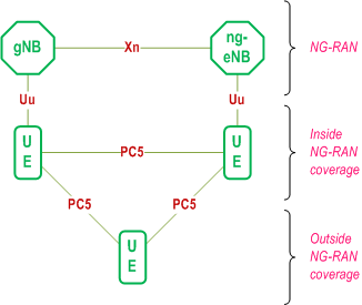
Support of V2X services via the PC5 interface can be provided by NR sidelink communication and/or V2X sidelink communication. NR sidelink communication may be used to support other services than V2X services.
NR sidelink communication can support one of three types of transmission modes for a pair of a Source Layer-2 ID and a Destination Layer-2 ID in the AS:
-
Unicast transmission, characterized by:
- Support of one PC5-RRC connection between peer UEs for the pair;
- Transmission and reception of control information and user traffic between peer UEs in sidelink;
- Support of sidelink HARQ feedback;
- Support of sidelink transmit power control;
- Support of RLC AM;
- Detection of radio link failure for the PC5-RRC connection.
-
Groupcast transmission, characterized by:
- Transmission and reception of user traffic among UEs belonging to a group in sidelink;
- Support of sidelink HARQ feedback.
-
Broadcast transmission, characterized by:
- Transmission and reception of user traffic among UEs in sidelink.
16.9.2 Radio Protocol Architecture for NR sidelink communication p. 167
16.9.2.1 Overview p. 167
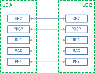
The AS protocol stack for the control plane for SCCH for RRC in the PC5 interface consists of RRC, PDCP, RLC and MAC sublayers, and the physical layer. The protocol stack of control plane for SCCH for RRC is shown in Figure 16.9.2.1-1.
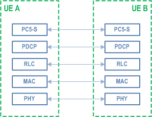
For support of PC5-S protocol specified in TS 23.287, PC5-S is located on top of PDCP, RLC and MAC sublayers, and the physical layer in the control plane protocol stack for SCCH for PC5-S, as shown in Figure 16.9.2.1-2.
The AS protocol stack for user plane in the PC5 interface consists of SDAP, PDCP, RLC and MAC sublayers, and the physical layer. The protocol stack of user plane is shown in Figure 16.9.2.1-4.
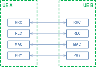
The AS protocol stack for user plane in the PC5 interface consists of SDAP, PDCP, RLC and MAC sublayers, and the physical layer. The protocol stack of PC5-U is shown in Figure 16.9.2.1-4.
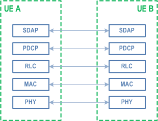
Sidelink Radio bearers (SLRB) are categorized into two groups: sidelink data radio bearers (SL DRB) for user plane data and sidelink signalling radio bearers (SL SRB) for control plane data. Separate SL SRBs using different SCCHs are configured for PC5-RRC and PC5-S signalling respectively.
16.9.2.2 MAC p. 168
The MAC sublayer provides the following services and functions over the PC5 interface in addition to the services and functions specified in clause 6.2.1:
- Radio resource selection;
- Packet filtering;
- Priority handling between uplink and sidelink transmissions for a given UE;
- Sidelink CSI reporting.
- Sidelink Control Channel (SCCH): a sidelink channel for transmitting control information (i.e. PC5-RRC and PC5-S messages) and NR sidelink discovery messages from one UE to other UE(s);
- Sidelink Traffic Channel (STCH): a sidelink channel for transmitting user information from one UE to other UE(s);
- Sidelink Broadcast Control Channel (SBCCH): a sidelink channel for broadcasting sidelink system information from one UE to other UE(s).
- SCCH can be mapped to SL-SCH;
- STCH can be mapped to SL-SCH;
- SBCCH can be mapped to SL-BCH.
16.9.2.3 RLC p. 169
The services and functions of the RLC sublayer as specified in clause 6.3.2 are supported for sidelink. TM is used for SBCCH. Both UM and AM are used in unicast transmission while only UM is used in groupcast or broadcast transmission. For UM, only unidirectional transmission is supported for groupcast and broadcast.
16.9.2.4 PDCP p. 169
The services and functions of the PDCP sublayer as specified in clause 6.4.1 are supported for sidelink with some restrictions:
- Out-of-order delivery is supported only for unicast transmission.
16.9.2.5 SDAP p. 169
The SDAP sublayer provides the following service and function over the PC5 interface:
- Mapping between a QoS flow and a sidelink data radio bearer.
16.9.2.6 RRC p. 169
The RRC sublayer provides the following services and functions over the PC5 interface:
- Transfer of a PC5-RRC message between peer UEs;
- Maintenance and release of a PC5-RRC connection between two UEs;
- Detection of sidelink radio link failure for a PC5-RRC connection;
- Measurement configuration and reporting related to sidelink.
16.9.3 Radio Resource Allocation p. 169
16.9.3.1 General p. 169
For NR sidelink communication, the UE can operate in two modes as specified in clause 5.7.2 for resource allocation in sidelink:
-
Scheduled resource allocation, characterized by:
- The UE needs to be RRC_CONNECTED in order to transmit data;
- NG-RAN schedules transmission resources.
-
UE autonomous resource selection, characterized by:
- The UE can transmit data when inside NG-RAN coverage, irrespective of which RRC state the UE is in, and when outside NG-RAN coverage;
- The UE autonomously selects transmission resources from resource pool(s).
16.9.3.2 Scheduled Resource Allocation p. 170
NG-RAN can dynamically allocate resources to the UE via the SL-RNTI on PDCCH(s) for NR sidelink communication.
In addition, NG-RAN can allocate sidelink resources to a UE with two types of configured sidelink grants:
- With type 1, RRC directly provides the configured sidelink grant only for NR sidelink communication;
- With type 2, RRC defines the periodicity of the configured sidelink grant while PDCCH can either signal and activate the configured sidelink grant, or deactivate it. The PDCCH is addressed to SL-CS-RNTI for NR sidelink communication.
16.9.3.3 UE Autonomous Resource Selection p. 170
The UE autonomously selects sidelink resource(s) from resource pool(s) provided by broadcast system information or dedicated signalling while inside NG-RAN coverage or by pre-configuration while outside NG-RAN coverage.
For NR sidelink communication, the resource pool(s) can be provided for a given validity area where the UE does not need to acquire a new pool of resources while moving within the validity area, at least when this pool is provided by SIB. The NR SIB area scope mechanism as specified in TS 38.331 is reused to enable validity area for SL resource pool configured via broadcasted system information.
The UE is allowed to temporarily use UE autonomous resource selection with random selection for sidelink transmission based on configuration of the exceptional transmission resource pool as specified in TS 38.331.
16.9.3.4 LTE and NR Sidelink co-channel coexistence |R18| p. 170
NR sidelink supports co-channel coexistence with LTE sidelink, allowing NR sidelink transmissions to share co-channel resources with LTE sidelink transmissions. Dynamic co-channel coexistence is used, in which a resource pool for NR sidelink transmissions is overlapping with a resource pool for LTE sidelink transmissions. Sidelink relay is not supported in a resource pool that uses dynamic co-channel coexistence. Dynamic co-channel coexistence is further specified in TS 38.321, TS 38.213 and TS 38.214.
16.9.4 Uu Control p. 170
16.9.4.1 General p. 170
When a UE is inside NG-RAN coverage, NR sidelink communication and/or V2X sidelink communication can be configured and controlled by NG-RAN via dedicated signalling or system information:
- The UE should support and be authorized to perform NR sidelink communication and/or V2X sidelink communication in NG-RAN;
- If configured, the UE performs V2X sidelink communication as specified in TS 36.300 unless otherwise specified, with the restriction that the dynamic scheduling for V2X sidelink communication (i.e. based on SL-V-RNTI) is not supported;
- NG-RAN can provide the UE with intra-carrier sidelink configuration, inter-carrier sidelink configuration and anchor carrier(s) which provide sidelink configuration via a Uu carrier for NR sidelink communication and/or V2X sidelink communication;
- When the UE cannot simultaneously perform both NR sidelink transmission and NR uplink transmission in time domain, prioritization between both transmissions is done based on their priorities and thresholds configured by the NG-RAN or pre-configured. When the UE cannot simultaneously perform both V2X sidelink transmission and NR uplink transmission in time domain, prioritization between both transmissions is done based on the priorities (i.e. PPPP) of V2X sidelink communication and a threshold configured by the NG-RAN or pre-configured.
16.9.4.2 Control of connected UEs p. 171
The UE in RRC_CONNECTED performs NR sidelink communication and/or V2X sidelink communication, as configured by the upper layers. The UE sends Sidelink UE Information to NG-RAN in order to request or release sidelink resources and report QoS information for each destination.
NG-RAN provides RRCReconfiguration to the UE in order to provide the UE with dedicated sidelink configuration. The RRCReconfiguration may include SL DRB configuration(s) for NR sidelink communication as well as mode 1 resource configuration and/or mode 2 resource configuration. If UE has received SL DRB configuration via system information, UE should continue using the configuration to perform sidelink data transmissions and receptions until a new configuration is received via the RRCReconfiguration.
NG-RAN may also configure measurement and reporting of CBR for NR sidelink communication and V2X sidelink communication, and reporting of location information for V2X sidelink communication to the UE via RRCReconfiguration.
During handover, the UE performs sidelink transmission and reception based on configuration of the exceptional transmission resource pool or configured sidelink grant Type 1 and reception resource pool of the target cell as provided in the handover command.
16.9.4.3 Control of idle/inactive UEs p. 171
The UE in RRC_IDLE or RRC_INACTIVE performs NR sidelink communication and/or V2X sidelink communication, as configured by the upper layers. NG-RAN may provide common sidelink configuration to the UE in RRC_IDLE or RRC_INACTIVE via system information for NR sidelink communication and/or V2X sidelink communication. UE receives resource pool configuration and SL DRB configuration via SIB12 for NR sidelink communication as specified in TS 38.331, and/or resource pool configuration via SIB13 and SIB14 for V2X sidelink communication as specified in TS 38.331.
When the UE performs cell reselection, the UE interested in V2X service(s) considers at least whether NR sidelink communication and/or V2X sidelink communication are supported by the cell. The UE may consider the following carrier frequency as the highest priority frequency, except for the carrier only providing the anchor carrier:
- the frequency providing both NR sidelink communication configuration and V2X sidelink communication configuration, if configured to perform both NR sidelink communication and V2X sidelink communication;
- the frequency providing NR sidelink communication configuration, if configured to perform only NR sidelink communication.
- the frequency providing V2X sidelink communication configuration, if configured to perform only V2X sidelink communication.
16.9.5 Sidelink Discovery |R17| p. 172
The UE may perform NR sidelink discovery while in-coverage or out-of-coverage for non-relay operation.
The Relay discovery mechanism described in clause 16.12.3 (except the U2N Relay specific threshold based discovery message transmission and U2N Relay specific resource allocation mode restriction) is also applied to sidelink discovery.
16.9.6 SL DRX |R17| p. 172
16.9.6.1 General p. 172
Sidelink supports SL DRX for unicast, groupcast, and broadcast. Similar parameters as defined in clause 11 for Uu (on-duration, inactivity-timer, retransmission-timer, cycle) are defined for SL to determine the SL active time for SL DRX. During the SL active time, the UE performs SCI monitoring for data reception (i.e., PSCCH and 2nd stage SCI on PSSCH). The UE may skip monitoring of SCI for data reception during SL DRX inactive time.
The actual parameters supported for each cast type (unicast, groupcast, broadcast) are specified in the following clauses.
The SL active time of the RX UE includes the time in which any of its applicable SL on-duration timer(s), SL inactivity-timer(s) or SL HARQ retransmission timer(s) (for any of unicast, groupcast, or broadcast) are running. In addition, the slots associated with announced periodic transmissions by the TX UE and the time in which a UE is expecting CSI report following a CSI request (for unicast) are considered as SL active time of the RX UE. The time for the unicast link establishment procedure and the time for the PC5 RRC reconfiguration with initial SL DRX configuration procedure as specified in clause 5.28.2 of TS 38.321 are considered as SL active time of the RX UE.
The TX UE maintains a set of timers corresponding to the SL DRX timers in the RX UE(s) for each pair of source/destination L2 ID for unicast or destination L2 ID for groupcast/broadcast. When data is available for transmission to one or more RX UE(s) configured with SL DRX, the TX UE selects resources taking into account the active time of the RX UE(s).
The UE can determine from SIB12 whether the gNB supports SL DRX or not.
16.9.6.2 Unicast p. 172
For unicast, SL DRX is configured per pair of source L2 ID and destination L2 ID.
The UE maintains a set of SL DRX timers for each direction per pair of source L2 ID and destination L2 ID. The SL DRX configuration for a pair of source/destination L2 IDs for a direction may be negotiated between the UEs in the AS layer. For SL DRX configuration of each direction, where one UE is the TX UE and the other is the RX UE:
- RX UE may send assistance information, which includes its desired SL on-duration timer, SL DRX start offset, SL DRX slot offset, and SL DRX cycle, to the TX UE and the TX UE using mode 2 resource allocation may use it to determine the SL DRX configuration for the RX UE;
- Regardless of whether assistance information is provided or not, the TX UE in RRC_IDLE/ RRC_INACTIVE/ OOC, or in RRC_CONNECTED and using mode 2 resource allocation, determines the SL DRX Configuration for the RX UE. For a TX UE in RRC_CONNECTED and using mode 1 resource allocation, the SL DRX configuration for the RX UE is determined by the serving gNB of the TX UE;
- TX UE sends the SL DRX configuration to be used by the RX UE to the RX UE;
- The RX UE may accept or reject the SL DRX configuration.
16.9.6.3 Groupcast/Broadcast p. 173
For groupcast/broadcast, SL DRX is configured commonly among multiple UEs based on QoS profile and Destination L2 ID. Multiple SL DRX configurations can be supported for each of groupcast/broadcast.
SL on-duration timer, SL inactivity-timer, SL HARQ RTT and SL HARQ retransmission timers are supported for groupcast. Only SL on-duration timer is supported for broadcast. SL DRX cycle, SL on-duration, and SL inactivity timer (only for groupcast) are configured per QoS profile. The starting offset and slot offset of the SL DRX cycle is determined based on the destination L2 ID. The SL HARQ RTT timer (only for groupcast) and SL HARQ retransmission timer (only for groupcast) are not configured per QoS profile or per destination L2 ID. For groupcast, the RX UE maintains a SL inactivity timer for each destination L2 ID, and selects the largest SL inactivity timer value if multiple SL inactivity timer values associated with different QoS profiles are configured for that L2 ID. For groupcast and broadcast, the RX UE maintains a single SL DRX cycle (selected as the smallest SL DRX cycle of any QoS profile of that L2 ID) and single SL on-duration (selected as the largest SL on-duration of any QoS profile of that L2 ID) for each destination L2 ID when multiple QoS profiles are configured for that L2 ID.
For groupcast, SL HARQ RTT timer and SL HARQ retransmission timer are maintained per SL process at the RX UE. SL HARQ RTT timer can be set to different values to support both HARQ enabled and HARQ disabled transmissions.
A default SL DRX configuration, common between groupcast and broadcast, can be used for a QoS profile which is not mapped onto any non-default SL DRX configuration(s). The default SL DRX configuration for groupcast and broadcast can also be used for discovery message in sidelink discovery in clause 16.9.5 and relay discovery messages in clause 16.12.3, for ProSe Direct Link Establishment Request message as specified in TS 24.554, and for Direct Link Establishment Request message as specified in TS 24.587.
In-coverage TX and RX UEs in RRC_IDLE/RRC_INACTIVE obtain their SL DRX configuration from SIB. UEs (TX or RX) in RRC_CONNECTED can obtain the SL DRX configuration from SIB, or from dedicated RRC signalling during handover. For the out of coverage case, the SL DRX configuration is obtained from pre-configuration.
For groupcast, the TX UE restarts its timer corresponding to the SL inactivity timer for the destination L2 ID (used for determining the allowable transmission time) upon reception of new data with the same destination L2 ID.
TX profile is introduced to ensure compatibility for groupcast and broadcast communication between UEs supporting/not-supporting SL DRX functionality. A TX profile is provided by upper layers to AS layer and identifies one or more sidelink feature group(s). Multiple TX profiles with the support of SL DRX and without the support of SL DRX can be associated to a destination L2 ID. For a given destination L2 ID, all TX and RX UEs should be configured with the same set of TX profile(s). A UE only assumes SL DRX for the given destination L2 ID when all the associated TX profiles correspond to support of SL DRX. A UE assumes no SL DRX for the given destination L2 ID if there is no associated TX profile. An RX UE determines that SL DRX is used if all destination L2 IDs of interest are assumed to support SL DRX. For groupcast, when the UE is in RRC_CONNECTED and using mode 1 resource allocation, the UE reports each destination L2 ID and associated SL DRX on/off indication to the gNB supporting SL DRX.
16.9.6.4 Alignment between Uu DRX and SL DRX p. 173
Alignment of Uu DRX and SL DRX for a UE in RRC_CONNECTED is supported for unicast, groupcast, and broadcast. Alignment of Uu DRX and SL DRX at the same UE is supported. In addition, for mode 1 resource allocation, the alignment of Uu DRX of the TX UE and SL DRX of the RX UE is supported.
Alignment may comprise of either full overlap or partial overlap in time between Uu DRX and SL DRX. For SL RX UEs in RRC_CONNECTED, alignment is achieved by the gNB.
16.9.7 Power Savings Resource Allocation |R17| p. 174
The SL UE in Mode 2 can support partial sensing-based resource allocation and random resource selection as power saving resource allocation methods. A SL mode 2 TX resource pool can be (pre)configured to allow full sensing only, partial sensing only, random selection only, or any combination(s) thereof. A UE decides which resource allocation scheme(s) can be used in the AS based on its capability (for a UE in RRC_IDLE/ RRC_INACTIVE/ OOC) and the allowed resource schemes in the resource pool configuration.
Random resource selection is applicable to both periodic and aperiodic traffic.
A UE capable for partial sensing can perform periodic-based partial sensing and/or contiguous partial sensing for resource (re)selection. Periodic-based partial sensing can only be performed if periodic resource reservation is configured in the resource pool. In periodic-based partial sensing, the UE monitors slots in periodic sensing occasion(s) for a given resource reservation periodicity. Contiguous partial sensing is performed by a UE capable of partial sensing when resource (re)selection is triggered by a UE in a TX pool configured with partial sensing. In contiguous partial sensing, the UE monitors slots in a contiguous sensing window which occur prior to the selected transmission resource.
16.9.8 Inter-UE Coordination (IUC) |R17| p. 174
The SL UE can support inter-UE coordination (IUC) in Mode 2, whereby a UE sends information about resources to a peer UE, which the peer UE then uses for resource (re)selection. The following schemes of inter-UE coordination are supported:
- IUC scheme 1, where the IUC information sent from a UE to a peer UE is the preferred or non-preferred resources for the peer UE's transmission, and
- IUC scheme 2, where the IUC information sent from a UE to a peer UE is the presence of expected/potential resource conflict on the resources indicated by the peer UE's SCI.
16.9.9 Sidelink in Shared Spectrum (SL-U) |R18| p. 174
16.9.9.1 Overview p. 174
Sidelink supports operation in shared spectrum for both mode 1 and mode 2 for ProSe use case only. Sidelink positioning in shared spectrum is not supported. Type1 and Type2 (2A/2B/2C) channel access procedures specified in TS 37.213 are used for NR sidelink operation in a shared channel.
16.9.9.2 Channel Access Priority Classes for Sidelink (SL-CAPC) p. 175
The SL-CAPC of SL radio bearers and SL MAC CEs are either fixed or (pre)configurable as follows:
- Fixed to the highest priority for all SL-SRBs and SL MAC CEs
- (Pre)configurable per DRB for all SL-DRBs
- if the QoS flow is associated with standardized PQI, the UE derives SL-CAPC for the flow directly from the Table below
- if the QoS flow is associated with non-standardized PQI, the UE may select the SL-CAPC of the standardized PQI having the closest PDB.
| SL-CAPC | PQI |
|---|---|
| 1 | 21, 22, 23, 24, 26, 55, 56, 57, 58, 60, 90, 91, 92, 93, 82, 83, 84, 85 |
| 2 | 25 |
| 3 | 59, 61 |
| 4 | - |
|
NOTE:
lower SL-CAPC value means higher priority
|
|
When performing Type 1 LBT for the transmission of a sidelink TB, the SL UE shall select the SL-CAPC as follows:
- If only SL MAC CE(s) are included in the SL TB, the highest priority SL-CAPC is used; or
- If SCCH SDU(s) are included in the SL TB, the highest priority SL-CAPC is used; or
- The lowest priority SL-CAPC of the SL logical channel(s) with MAC SDU(s) multiplexed in the TB is used otherwise.
16.9.9.3 Sidelink Specific Consistent LBT Failure p. 175
SL-specific consistent LBT failure detection and recovery procedure is supported for SL-U. When the UE detects SL-specific consistent LBT failure, it performs the actions as specified in TS 38.321. SL-specific consistent LBT failure detection is per RB-set.
A SL UE in RRC_CONNECTED can indicate SL-specific consistent LBT failure to the gNB using a SL MAC CE that indicates the RB set(s) where SL-specific consistent LBT failure was detected. A SL UE using mode 2 resource allocation triggers resource reselection and/or resource pool reselection upon SL-specific consistent LBT failure. In such case, resources in failed RB set(s) are excluded from resource (re)selection until consistent LBT failure on the RB set(s) is cancelled based on conditions in TS 38.321. The UE triggers SL RLF for all PC5-RRC connections when the UE has triggered SL-specific consistent LBT failure in all RB sets.
16.9.9.4 COT Sharing p. 175
UE to UE COT sharing is supported in NR sidelink operation for SL-U. When performing SL-SSB transmission(s), a responding UE can utilize a COT shared by a COT initiating UE when the responding UE intends to transmit SL-SSB in the shared COT. When performing PSFCH transmissions, a responding UE can utilize a COT shared by a COT initiating UE when at least one of the responding UE's PSFCH transmissions is intended for the COT initiating UE.
When performing PSSCH/PSCCH transmissions, a responding UE can utilize a COT shared by a COT initiating UE when the responding UE's transmission(s) is intended for the COT initiating UE. In unicast, the destination/source ID of the responding UE's transmission should match the source/destination ID of the initiator UE's transmission for the same unicast link. In groupcast/broadcast, destination ID of the responding UE's transmission should match the initiator's destination ID. In addition, a COT initiating UE may transmit an additional pair of source/destination ID in either unicast, groupcast, or broadcast. In this case, the responding UE can utilize a COT shared by a COT initiating UE if the destination/source (for unicast) or destination (for groupcast/broadcast) of the responding UE transmission match what is carried in the additional ID(s). In all cases, a UE's transmissions in a shared COT should have SL-CAPC value that is equal to or smaller than the SL-CAPC value indicated in the COT sharing information. In order to satisfy the COT sharing requirements, a responding UE may perform an enhanced LCP procedure as specified in 38.321 [6]. When receiving multiple COT sharing indications from different COT initiators, it is up to UE implementation which shared COT is used.
16.9.9.5 Resource Allocation p. 176
A UE using mode 2 resource allocation may support resource selection enhancements to avoid LBT blocking and increase COT resource utilization. If transmission in slot(s) before a reserved resource is able to share its initiated COT to the reservation, the UE may be (pre)configured to prioritize/select resource(s) in the slot(s) for transmission. To avoid blocking, a UE may avoid selection of a number of consecutive resources (up to UE implementation) before a reserved resource. Furthermore, a UE may avoid selection of a number of consecutive resources (up to UE implementation) after a reserved resource.
A UE using mode 2 resource allocation supports resource selection for multiple consecutive slot transmission (MCSt). A UE autonomously determines whether to use MCSt, and the number of consecutive slots in an MCSt up to the maximum COT duration for a specific SL-CAPC as defined in TS 37.213. MCSt can be used for transmission of a single TB or multiple TBs. For each TB transmitted in an MCSt, the UE triggers resource (re)selection only when LBT failure is detected on the resources for the initial transmission and all retransmissions of the TB.
16.9.10 Sidelink CA |R18| p. 176
Carrier aggregation (CA) in sidelink is supported for mode 2 and in V2X case only. It applies to both in coverage UEs and out of coverage UEs. Each resource pool (pre)configured for sidelink is associated to a single carrier. A UE using mode 2 resource allocation performs carrier (re)selection and may select one or more carriers used for sidelink.
The carrier(s) that can be used for transmitting data are provided by the V2X layer per QoS flow, and LCP ensures that data from a SLRB is transmitted on a carrier for which all mapped QoS flows are allowed to use the carrier.
For groupcast and broadcast, when the V2X layer provides multiple carriers in QoS flow to carrier mapping information to the AS, TX profile is used to indicate whether the transmission corresponding to the QoS flow is backward compatible or not. When backward compatibility is needed, the TX UE uses only the legacy carrier without PDCP duplication, or uses PDCP duplication with at least the legacy carrier. A UE assumes backward compatibility is needed for the QoS flow if there is no associated TX profile.
For groupcast and broadcast, carrier selection is performed at MAC layer, depending on the CBR of the configured carriers and logical channel priority. In order to avoid frequent switching across different carriers, the UE may keep using a carrier already selected for transmission, if the measured CBR on this carrier is lower than a (pre)configured threshold. For a UE using mode 2 resource allocation, logical channel prioritization is performed for a sidelink resource on a carrier depending on the CBR measured on the carrier and the logical channel priority, as specified in TS 38.321. For unicast, SL CA related capability is exchanged between the TX UE and RX UE, and the TX UE delivers the carrier configuration to the RX UE in PC5-RRC. For unicast, carrier selection and logical channel prioritization is performed similar to groupcast and broadcast among the carriers configured in the carrier configuration. SL CA for unicast is not applied until the carrier configuration signalling is complete. When the TX UE detects carrier failure on a specific carrier, carrier (re)selection is performed by excluding the failed carrier, as specified in TS 38.321 and a new carrier configuration is sent to the RX UE as specified in TS 38.331.
Sidelink packet duplication is supported for sidelink CA and is performed at PDCP layer. For sidelink packet duplication for transmission, a PDCP PDU is duplicated at the PDCP entity. The duplicated PDCP PDUs of the same PDCP entity are submitted to two different RLC entities and associated to two different sidelink logical channels respectively. The duplicated PDCP PDUs of the same PDCP entity are only allowed to be transmitted on different sidelink carriers. For a SL DRB, sidelink packet duplication is either (pre)configured in the bearer configuration if the TX profile indicates backward compatibility is not needed, or is decided by the TX UE if the TX profile indicates backward compatibility is needed. For applicable SL SRBs, whether to use duplication is decided by the TX UE. In unicast, the TX UE sends the duplication configuration to the RX UE in PC5-RRC.
There are specified logical channel identities which apply to the sidelink logical channel used for sidelink packet duplication exclusively as specified in TS 38.321.