Content for TS 38.300 Word version: 18.4.0
1…
4…
4.7…
5…
5.3…
5.4…
6…
6.2…
6.6…
7…
8…
9…
9.2.2…
9.2.2.5…
9.2.3…
9.2.3.2…
9.2.3.3…
9.2.4…
9.2.6…
9.3…
10…
11…
15…
15.5…
16…
16.2…
16.3…
16.4…
16.8…
16.9…
16.10…
16.12…
16.12.5…
16.12.6…
16.12.6.3
16.12.7
16.13…
16.14…
16.15…
16.18…
16.19…
16.21…
16.21.3…
17…
18…
19
20…
21…
A…
B…
C…
G…
15 Self-Configuration and Self-Optimisation
15.1 Definitions
15.3 Self-configuration
15.3.1 Dynamic configuration of the NG-C interface
15.3.1.1 Prerequisites
15.3.1.2 SCTP initialization
15.3.1.3 Application layer initialization
15.3.2 Dynamic Configuration of the Xn interface
15.3.2.1 Prerequisites
15.3.2.2 SCTP initialization
15.3.2.3 Application layer initialization
15.3.3 Automatic Neighbour Cell Relation Function
15.3.3.1 General
15.3.3.2 Intra-system Automatic Neighbour Cell Relation Function
15.3.3.5 Inter-system Automatic Neighbour Cell Relation Function
15.3.4 Xn-C TNL address discovery
15.4 Support for Energy Saving
15.4.1 General
15.4.2 Solution description
15.4.2.1 Intra-system energy saving
15.4.2.2 Inter-system energy saving
15.4.2.3 Cell DTX/DRX
15.4.2.4 Conditional Handover
15.4.2.5 Camping Restrictions
15.4.2.6 SSB-less SCell
15.4.2.7 Spatial and power domain adaptation
15.4.3 O&M requirements
...
...
15 Self-Configuration and Self-Optimisation p. 134
15.1 Definitions p. 134
Void.
15.2 Void
15.3 Self-configuration p. 134
15.3.1 Dynamic configuration of the NG-C interface p. 134
15.3.1.1 Prerequisites p. 134
The following prerequisites are assumed:
- An initial remote IP end point to be used for SCTP initialisation is provided to the NG-RAN node for each AMF the NG-RAN node is supposed to connect to.
15.3.1.2 SCTP initialization p. 134
NG-RAN establishes the first SCTP (IETF RFC 4960) using a configured IP address.
15.3.1.3 Application layer initialization p. 134
Once SCTP connectivity has been established, the NG-RAN node and the AMF shall exchange application level configuration data over NGAP with the NG Setup procedure, which is needed for these two nodes to interwork correctly on the NG interface:
- The NG-RAN node provides the relevant configuration information to the AMF, which includes list of supported TA(s), etc.;
- The AMF provides the relevant configuration information to the NG-RAN node, which includes PLMN ID, etc.;
- When the application layer initialization is successfully concluded, the dynamic configuration procedure is completed and the NG-C interface is operational.
15.3.2 Dynamic Configuration of the Xn interface p. 134
15.3.2.1 Prerequisites p. 134
The following prerequisites are necessary:
- An initial remote IP end point to be used for SCTP initialisation is provided to the NG-RAN node.
15.3.2.2 SCTP initialization p. 134
NG-RAN establishes the first SCTP (IETF RFC 4960) using a configured IP address.
15.3.2.3 Application layer initialization p. 135
Once SCTP connectivity has been established, the NG-RAN node and its candidate peer NG-RAN node are in a position to exchange application level configuration data over XnAP needed for the two nodes to interwork correctly on the Xn interface:
- The NG-RAN node provides the relevant configuration information to the candidate NG-RAN node, which includes served cell information;
- The candidate NG-RAN node provides the relevant configuration information to the initiating NG-RAN node, which includes served cell information;
- When the application layer initialization is successfully concluded, the dynamic configuration procedure is completed and the Xn interface is operational;
- The NG-RAN node shall keep neighbouring NG-RAN nodes updated with the complete list of served cells, or, if requested by the peer NG-RAN node, by a limited list of served cells, while the Xn interface is operational.
15.3.3 Automatic Neighbour Cell Relation Function p. 135
15.3.3.1 General p. 135
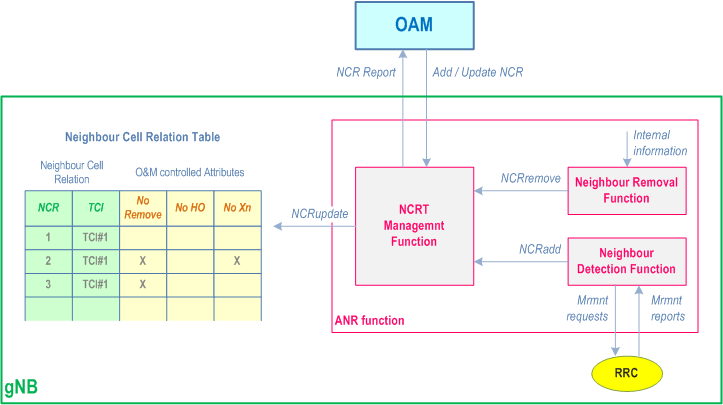
The purpose of ANR function is to relieve the operator from the burden of manually managing NCRs. Figure 15.3.3.1-1 shows ANR and its environment:

The ANR function resides in the gNB and manages the Neighbour Cell Relation Table (NCRT). Located within ANR, the Neighbour Detection Function finds new neighbours and adds them to the NCRT. ANR also contains the Neighbour Removal Function which removes outdated NCRs. The Neighbour Detection Function and the Neighbour Removal Function are implementation specific.
An existing NCR from a source cell to a target cell means that gNB controlling the source cell:
- Knows the global and physical IDs (e.g. NR CGI/NR PCI, ECGI/PCI) of the target cell; and
- Has an entry in the NCRT for the source cell identifying the target cell; and
- Has the attributes in this NCRT entry defined, either by OAM or set to default values.
15.3.3.2 Intra-system Automatic Neighbour Cell Relation Function p. 136
ANR relies on NCGI (see clause 8.2) and ANR reporting of E-UTRA cells as specified in TS 36.300.

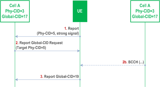
Figure 15.3.3.2-1 depicts an example where the NG-RAN node serving cell A has an ANR function. In RRC_CONNECTED, the NG-RAN node instructs each UE to perform measurements on neighbour cells. The NG-RAN node may use different policies for instructing the UE to do measurements, and when to report them to the NG-RAN node. This measurement procedure is as specified in TS 38.331 and TS 36.331.
Step 1.
When the NG-RAN node receives a UE measurement report containing the PCI, the following sequence may be used.
The UE sends a measurement report regarding cell B. This report contains Cell B's PCI, but not its NCGI/ECGI.
Step 2.
The NG-RAN node instructs the UE, using the newly discovered PCI as parameter, to read all the broadcast NCGI(s) /ECGI(s), TAC(s), RANAC(s), PLMN ID(s) and, for neighbour NR cells, NR frequency band(s) and the gNB ID length(s). To do so, the NG-RAN node may need to schedule appropriate idle periods to allow the UE to read the NCGI/ECGI from the broadcast channel of the detected neighbour cell. How the UE reads the NCGI/ECGI is specified in TS 38.331 and TS 36.331.
Step 3.
When the UE has found out the new cell's NCGI(s) /ECGI(s), the UE reports all the broadcast NCGI(s)/ECGI(s) to the serving cell NG-RAN node. In addition, the UE reports all the tracking area code(s), RANAC(s), PLMN IDs and, for neighbour NR cells, NR frequency band(s), and the gNB ID length(s) that have been read by the UE. In case the detected NR cell does not broadcast SIB1, the UE may report noSIB1 indication as specified in TS 38.331.
Step 4.
The NG-RAN node decides to add this neighbour relation, and can use PCI and NCGI(s)/ECGI(s) to:
- Lookup a transport layer address to the new NG-RAN node;
- Update the Neighbour Cell Relation List;
- If needed, setup a new Xn interface towards this NG-RAN node.
15.3.3.3 Void
15.3.3.4 Void
15.3.3.5 Inter-system Automatic Neighbour Cell Relation Function p. 137
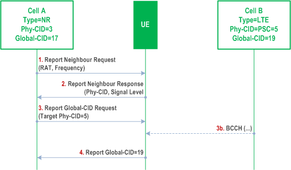
For Inter-system ANR, each cell contains an Inter Frequency Search list. This list contains all frequencies that shall be searched. Figure 15.3.3.5-1 depicts an example where the NG-RAN node serving cell A has an ANR function.

In RRC_CONNECTED, the NG-RAN node instructs a UE to perform measurements and detect E-UTRA cells connected to EPC.:
Step 1.
When the NG-RAN node receives the UE reports containing PCIs of cell(s), the following sequence may be used:
The NG-RAN node instructs a UE to look for neighbour cells in the target system. To do so the NG-RAN node may need to schedule appropriate idle periods to allow the UE to scan all cells in the target system.
Step 2.
The UE reports the PCI and carrier frequency of the detected cells in the target system.
Step 3.
The NG-RAN node instructs the UE, using the newly discovered PCI as parameter, to read the ECGI, the TAC and all available PLMN ID(s) of the newly detected cell in case of E-UTRA detected cells. The UE ignores transmissions from the serving cell while finding the requested information transmitted in the broadcast channel of the detected inter-system/inter-frequency neighbour cell. To do so, the NG-RAN node may need to schedule appropriate idle periods to allow the UE to read the requested information from the broadcast channel of the detected inter-system neighbour cell.
Step 4.
After the UE has read the requested information in the new cell, it reports the detected ECGI, TAC, and available PLMN ID(s) to the serving cell NG-RAN node.
Step 5.
The NG-RAN node updates its inter-system NCRT.
15.3.4 Xn-C TNL address discovery p. 137
If the NG-RAN node is aware of the RAN node ID of the candidate NG-RAN node (e.g. via the ANR function) but not of a TNL address suitable for SCTP connectivity, then the NG-RAN node can utilize the 5GC (an AMF it is connected to) to determine the TNL address as follows:
- The NG-RAN node sends the UPLINK RAN CONFIGURATION TRANSFER message to the AMF to request the TNL address of the candidate NG-RAN node, and includes relevant information such as the source and target RAN node ID;
- The AMF relays the request by sending the DOWNLINK RAN CONFIGURATION TRANSFER message to the candidate NG-RAN node identified by the target RAN node ID;
- The candidate NG-RAN node responds by sending the UPLINK RAN CONFIGURATION TRANSFER message containing one or more TNL addresses to be used for SCTP connectivity with the initiating NG-RAN node, and includes other relevant information such as the source and target RAN node ID;
- The AMF relays the response by sending the DOWNLINK CONFIGURATION TRANSFER message to the initiating NG-RAN node identified by the target RAN node ID.
15.4 Support for Energy Saving p. 138
15.4.1 General p. 138
The aim of this function is to reduce operational expenses through energy savings.
The function allows, for example in a deployment where capacity boosters can be distinguished from cells providing basic coverage, to optimize energy consumption enabling the possibility for an E-UTRA or NR cell providing additional capacity via single or dual connectivity, to be switched off when its capacity is no longer needed and to be re-activated on a need basis, or to support various adaptation techniques in time, frequency, spatial and power domains.
15.4.2 Solution description p. 138
15.4.2.1 Intra-system energy saving |R17| p. 138
The solution builds upon the possibility for the NG-RAN node owning a capacity booster cell to autonomously decide to switch-off such cell to lower energy consumption (inactive state). The decision is typically based on cell load information, consistently with configured information. The switch-off decision may also be taken by O&M.
The NG-RAN node may initiate handover actions in order to off-load the cell being switched off and may indicate the reason for handover with an appropriate cause value to support the target node in taking subsequent actions, e.g. when selecting the target cell for subsequent handovers.
All neighbour NG-RAN nodes are informed by the NG-RAN node owning the concerned cell about the switch-off actions over the Xn interface, by means of the NG-RAN node Configuration Update procedure.
All informed nodes maintain the cell configuration data, e.g., neighbour relationship configuration, also when a certain cell is inactive. If basic coverage is ensured by NG-RAN node cells, NG-RAN node owning non-capacity boosting cells may request a re-activation over the Xn interface if capacity needs in such cells demand to do so. This is achieved via the Cell Activation procedure. During switch off time period of the boost cell, the NG-RAN node may prevent idle mode UEs from camping on this cell and may prevent incoming handovers to the same cell.
The NG-RAN node receiving a request should act accordingly. The switch-on decision may also be taken by O&M. All peer NG-RAN nodes are informed by the NG-RAN node owning the concerned cell about the re-activation by an indication on the Xn interface.
The solution also builds upon the possibility for the NG-RAN node owning a coverage cell to request neighbouring NG-RAN node(s) owning a capacity booster cell to switch on some SSB beams within the cell which are deactivated. The receiving NG-RAN node should act accordingly.
The solution also builds upon the possibility for an NG-RAN node to page certain UEs (e.g., stationary UEs) in RRC_INACTIVE state on a limited set of beams, instead of paging on all the beams within the cell. It is up to the gNB's implementation to select the UEs in RRC_INACTIVE for which paging in limited set of beams applies. If the paging over the limited set of beams fails, the gNB performs subsequent paging by implementation, e.g., by ensuring the same paging message is repeated in all the transmitted SSB beams.
15.4.2.2 Inter-system energy saving |R17| p. 139
The solution builds upon the possibility for the NG-RAN node owning a capacity booster cell to autonomously decide to switch-off such cell to dormant state. The decision is typically based on cell load information, consistently with configured information. The switch-off decision may also be taken by O&M. The NG-RAN node indicates the switch-off action to the eNB over NG interface and S1 interface. The NG-RAN node could also indicate the switch-on action to the eNB over NG interface and S1 interface.
The eNB providing basic coverage may request a NG-RAN node's cell re-activation based on its own cell load information or neighbour cell load information, the switch-on decision may also be taken by O&M. The eNB requests a NG-RAN node's cell re-activation and receives the NG-RAN node's cell re-activation reply from the NG-RAN node over the S1 interface and NG interface. Upon reception of the re-activation request, the NG-RAN node's cell should remain switched on at least until expiration of the minimum activation time. The minimum activation time may be configured by O&M or be left to the NG-RAN node's implementation.
15.4.2.3 Cell DTX/DRX |R18| p. 139
To facilitate reducing gNB downlink transmission/uplink reception active time, UE can be configured with a periodic cell DTX/DRX pattern (i.e. active and non-active periods). The pattern configuration for cell DTX/DRX is common for the UEs configured with this feature in the cell. The cell DTX and cell DRX patterns can be configured and activated separately. A maximum of two cell DTX/DRX patterns can be configured per MAC entity for different serving cells. When cell DTX is configured and activated for the concerned cell, the UE may not monitor PDCCH in selected cases or does not monitor SPS occasions during cell DTX non-active duration. When cell DRX is configured and activated for the concerned cell, the UE does not transmit on CG resources or does not transmit a SR during cell DRX non-active duration. This feature is only applicable to UEs in RRC_CONNECTED state and it does not impact Random Access procedure, SSB transmission, paging, and system information broadcasting. Cell DTX/DRX operation is only supported for single TRP scenario. Cell DTX/DRX can be activated/deactivated by RRC signalling or L1 group common signalling. Cell DTX/DRX is characterized by the following:
- active duration: duration that the UE waits for to receive PDCCHs or SPS occasions, and transmit SR or CG. In this duration, the gNB transmission/reception of PDCCH, SPS, SR, CG, periodic and semi-persistent CSI report are not impacted for the purpose of network energy saving;
- cycle: specifies the periodic repetition of the active-duration followed by a period of non-active duration.
15.4.2.4 Conditional Handover |R18| p. 139
The same principle as described in clause 9.2.3.4 applies to conditional handover in case the source cell is using a network energy saving solution (e.g., the cell is activating cell DTX/DRX or turning off), unless hereunder specified. In this case, the following additional triggering conditions are supported, upon which UE may use NES-specific CHO event for executing CHO to a candidate cell, as defined in TS 38.331:
- The UE may be notified via DCI to enable CHO conditions(s) configured with NES event indication.
15.4.2.5 Camping Restrictions |R18| p. 139
If a cell is activating or going to activate NES cell DTX/DRX, the cell can allow the access of UEs capable of NES cell DTX/DRX via a single bit in SIB1 but prevent the access of UEs not capable of cell DTX/DRX using barring mechanisms described in clause 7.4.
15.4.2.6 SSB-less SCell |R18| p. 140
For an intra-band or inter-band CA SCell, a UE may obtain timing reference and AGC source from another serving cell in case the UE is not provided with SSB nor SMTC configuration for this SCell, as described in TS 38.331.
15.4.2.7 Spatial and power domain adaptation |R18| p. 140
To assist the gNB on muting transceivers and/or adapting transmission power, the UE can be configured to report multiple CSI entries in a CSI report based on two or more sub-configurations, as specified in clause 5.2.1.6 of TS 38.214. Each sub-configuration corresponds to a spatial domain adaptation pattern (subsets of available spatial elements) and/or a power offset between PDSCH and CSI-RS.
15.4.3 O&M requirements p. 140
Operators should be able to configure the energy saving function.
The configured information should include:
- The ability of an NG-RAN node to perform autonomous cell switch-off;
- The ability of an NG-RAN node to request the re-activation of a configured list of inactive cells owned by a peer NG-RAN node.
- policies used by the NG-RAN node for cell switch-off decision;
- policies used by peer NG-RAN nodes for requesting the re-activation of an inactive cell;
- The minimum time an NG-RAN node's cell should remain activated upon reception of a re-activation request from an eNB.