Content for TS 38.300 Word version: 18.4.0
1…
4…
4.7…
5…
5.3…
5.4…
6…
6.2…
6.6…
7…
8…
9…
9.2.2…
9.2.2.5…
9.2.3…
9.2.3.2…
9.2.3.3…
9.2.4…
9.2.6…
9.3…
10…
11…
15…
15.5…
16…
16.2…
16.3…
16.4…
16.8…
16.9…
16.10…
16.12…
16.12.5…
16.12.6…
16.12.6.3
16.12.7
16.13…
16.14…
16.15…
16.18…
16.19…
16.21…
16.21.3…
17…
18…
19
20…
21…
A…
B…
C…
G…
16.21 Multi-path Relay
16.21.1 General
16.21.2 Protocol Architecture
16.21.2.1 L2 MP Relay using SL indirect path
16.21.2.2 L2 MP Relay using N3C indirect path
...
...
16.21 Multi-path Relay |R18| p. 223
16.21.1 General p. 223
In multi-path relay scenario, a MP Remote UE is connected to a single gNB via one direct path and one indirect path while the MP Remote UE is in RRC_CONNECTED state. For the indirect path, both L2 and L3 MP Relay architectures are supported for MP Relay using PC5 interface, and only L2 MP Relay architecture is supported for MP Relay using N3C interface. The L3 MP Relay architecture is transparent to the serving NG-RAN of the MP Relay UE, except for controlling sidelink resources. In the case of MP Remote UE using SL indirect path, mode 1 resource allocation is supported only for intra-DU case, with the SR/BSR and grant sent on the direct path.
In multi-path relay, the interface between MP Remote UE and MP Relay UE can be either PC5 or N3C. When the interface between MP Remote UE and MP Relay UE is N3C interface, the relationship of MP Remote UE and MP Relay UE is pre-configured or static, and it is up to the implementation of the MP Remote UE and MP Relay UE how to pre-configure or make it static.
Multi-path relay supports MP Remote UE and MP Relay UE when they are in the same gNB, and PCell is always on the direct path.
Multi-path relay is supported in the following cell deployment scenarios:
- The MP Relay UE and MP Remote UE are served by the same cell;
- The MP Relay UE and MP Remote UE are served by different intra-frequency cells of the same gNB;
- The MP Relay UE and MP Remote UE are served by different inter-frequency cells of the same gNB.
- Sidelink TX/RX and Uu link share the same carrier at the MP Remote UE;
- Sidelink TX/RX and Uu link use different carriers at the MP Remote UE;
- Sidelink TX/RX and Uu link share the same carrier at the MP Relay UE;
- Sidelink TX/RX and Uu link use different carriers at the MP Relay UE.
16.21.2 Protocol Architecture p. 224
From L2 MP Remote UE perspective, three bearer types exist: direct bearer, indirect bearer, and split bearer. For direct bearer, only Uu radio resources are involved, and for indirect bearer, only PC5 or N3C radio resources are involved. For split bearer, both Uu and PC5/N3C radio resources are involved.
16.21.2.1 L2 MP Relay using SL indirect path p. 224
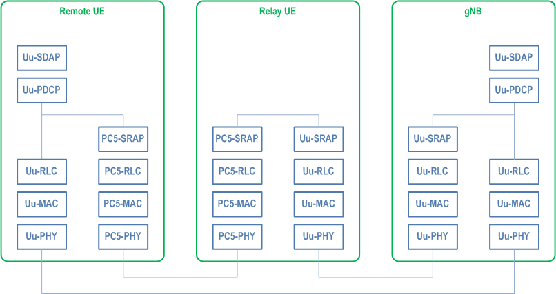
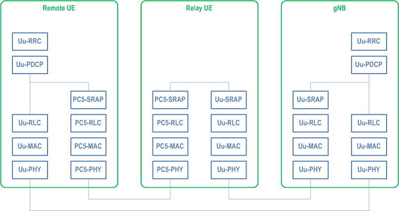
For multi-path relay operation by using SL indirect path, the protocol stacks for the user plane and control plane of L2 MP Relay architecture are illustrated in Figure 16.21.2.1-1 and Figure 16.21.2.1-2.
If PC5 interface is used between L2 MP Remote UE and L2 MP Relay UE, the SRAP sublayer is placed above the RLC sublayer for both CP and UP at both PC5 interface and Uu interface of the indirect path. For the direct path, the Uu SDAP, PDCP, RLC, MAC, PHY, and RRC are terminated at gNB and L2 MP Remote UE. But for the indirect path, only the Uu SDAP, PDCP and RRC are terminated at gNB and L2 MP Remote UE, while SRAP, RLC, MAC, and PHY are terminated in each hop (i.e., the link between L2 MP Remote UE and L2 MP Relay UE and the link between L2 MP Relay UE and the gNB). PDCP duplication is supported for the MP split bearer.


16.21.2.2 L2 MP Relay using N3C indirect path p. 225
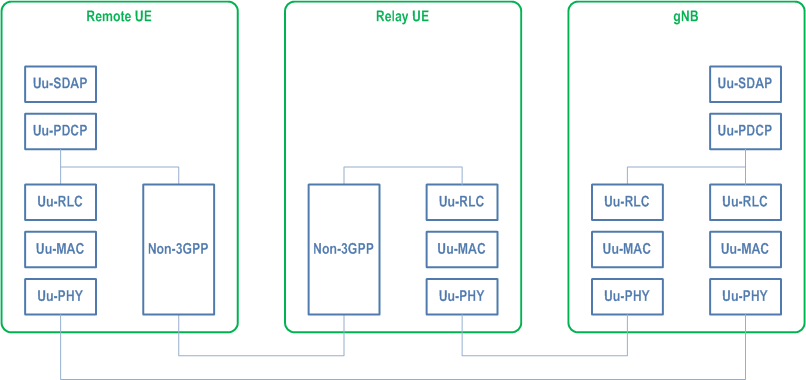
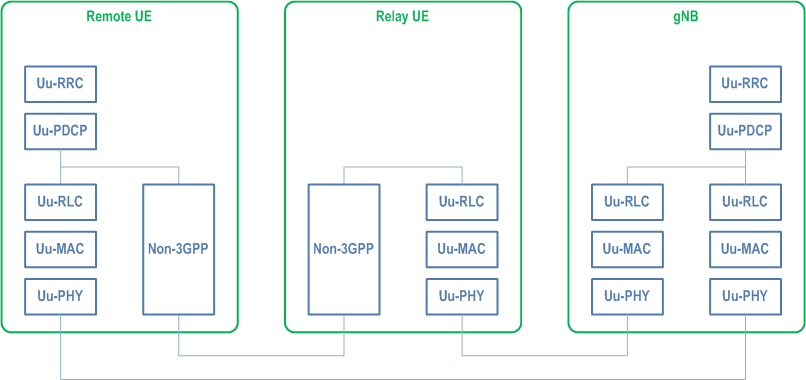
For the multi-path relay using N3C indirect path between the L2 MP Remote UE and L2 MP Relay UE, the protocol stacks for the user plane and control plane of L2 MP Relay architecture are illustrated in Figure 16.21.2.2-1 and Figure 16.21.2.2-2.
In the multi-path relay using N3C indirect path, the SRAP sublayer does not exist on the protocol stack. For the direct path, the Uu SDAP, PDCP, RLC, MAC, PHY and RRC are terminated at gNB and L2 MP Remote UE. While RLC, MAC, and PHY in Uu hop of indirect path are terminated at L2 MP Relay UE and gNB. Without the SRAP sublayer over N3C, an UL PDCP PDU in the L2 MP Remote UE is delivered to RLC entity in the L2 MP Relay UE via N3C link based on UE implementation. It is supported for more than one RB over the Uu link of the L2 MP Relay UE by configuring 1:1 bearer mapping between the Radio bearer in the L2 MP Remote UE and Uu Relay RLC channel in the L2 MP Relay UE. The Uu logical channels for the PDU delivery of the L2 MP Relay UE's local traffic and relay traffic are configured differently. Bearer identification except LCID is not needed in L2 PDU over the Uu link. If the split bearer is configured and the PDCP duplication is activated, the duplicated PDCP PDUs are delivered via both direct path and indirect path.

