Content for TS 23.435 Word version: 19.3.0
0…
4…
5…
7…
9…
9.4…
9.5…
9.6…
9.7…
9.8…
9.9…
9.10…
9.11…
9.12…
9.13…
9.14…
9.15…
9.16…
9.17…
9.18…
A…
7 Application architecture for NSCE
7.1 General
7.2 Architecture description
7.3 Functional entities description
7.4 Reference points description
8 Identities and commonly used values
8.1 General
8.2 NSCE server ID
8.3 NSCE client ID
8.4 Network Slice related Identifier
8.5 Slice coverage area
8.6 NSCE service area
...
...
7 Application architecture for NSCE p. 19
7.1 General p. 19
The architecture for the network slice capability enablement is based on the generic functional model specified in clause 6.2 of TS 23.434. It is organized into functional entities to describe a functional architecture which addresses the support for network slice capability enablement aspects for vertical applications. Since the slicing is a feature which considers the Uu interfaces, only the on-network functional model is specified in this clause.
7.2 Architecture description p. 19
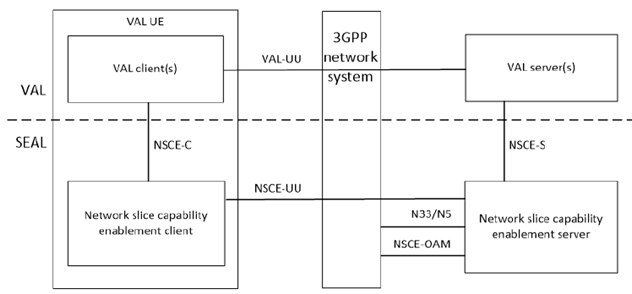
Figure 7.2-1 depicts the network slice capability enablement architecture in the non-roaming case, using the reference point representation showing how various entities interact with each other.

Figure 7.2-1: Architecture for network slice capability enablement - reference points representation
The network slice capability enablement client communicates with the network slice capability enablement server over the NSCE-UU reference point. The network slice capability enablement client provides the support for network slice capability enablement functions to the VAL client(s) over NSCE-C reference point. The VAL server(s) communicates with the network slice capability enablement server over the NSCE-S reference point. It is assumed that the network slice capability enablement server is deployed at the 5G system domain. The network slice capability enablement server, acting as AF, may communicate with the 5G Core Network functions via NEF (N33) reference point (for interactions with PCF, NSACF, etc.). The network slice capability enablement server may interact with OAM system over NSCE-OAM reference point, as consumer in both NSaaS and NoP model defined in the clause 4.1.6 and clause 4.1.7 of TS 28.530 (for Network Slice Provisioning capabilities, Performance Assurance, Fault Supervision etc.).
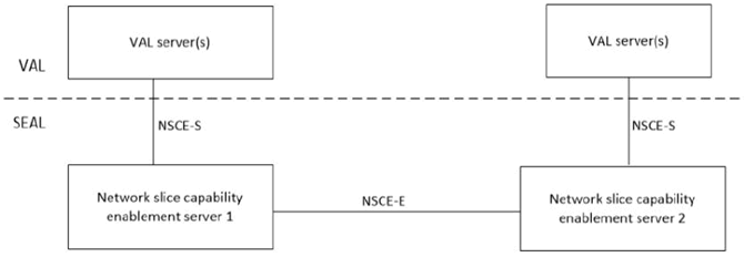
Figure 7.2-2 illustrates the architecture for interconnection between NSCE servers.

The NSCE server could interact with another NSCE server over NSCE-E reference point.
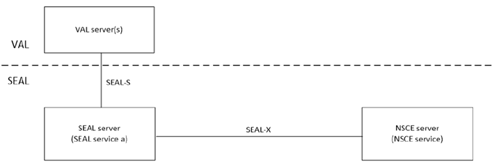
Figure 7.2-3 illustrates the architecture for inter-service communication between NSCE servers and other SEAL server.

The NSCE server interacts with another SEAL server for inter-service communication over SEAL-X reference point.
7.3 Functional entities description p. 20
7.3.1 General p. 20
The functional entities for network slice capability enablement SEAL service are described in the following subclauses.
7.3.2 Network slice capability enablement server p. 21
The network slice capability enablement server functional entity provides the application layer enablement of the network slicing aspects to support the VAL applications. The network slice capability enablement server acts as CAPIF's API exposing function as specified in TS 23.222.
7.3.3 Network slice capability enablement client p. 21
The network slice capability enablement client functional entity acts as the application client for the slice enablement. The network slice capability enablement client interacts with the network slice capability enablement server to trigger network slice related operations such as adaptation due to an application requirement change. This trigger may be due to an application QoS requirement change, a service operation change. The NSCE client may receive a network slice / DNN re-mapping notification from the NSCE server. The NSCE client may optionally notify the VAL client on the network slice / DNN re-mapping.
7.4 Reference points description p. 21
7.4.1 General p. 21
The reference points for the functional model for network slice capability enablement are described in the following subclauses.
7.4.2 NSCE-UU p. 21
The interactions related to network slice capability enablement functions between the network slice capability enablement server and the network slice capability enablement client are supported by NSCE-UU reference point. This reference point utilizes Uu reference point as described in TS 23.501.
7.4.3 NSCE-C p. 21
The interactions related to network slice capability enablement functions between the VAL client(s) and the network slice capability enablement client within a VAL UE are supported by the NSCE-C reference point. The NSCE client may receive application requirement change, application client information (such as its KQI) over NSCE-C. Further, the NSCE client may provide a notification on the network slice adaptation upon successful adaptation of the slice to application mapping.
7.4.4 NSCE-S p. 21
The interactions related to network slice capability enablement functions between the VAL server(s) and the network slice capability enablement server are supported by the NSCE-S reference point. This reference point is an instance of CAPIF-2 reference point as specified in TS 23.222.
7.4.5 N33 p. 21
The reference point N33 supports the interactions between the network slice capability enablement server and the NEF and is specified in TS 23.501. N33 is used for the network-based mechanism for slice re-mapping, where NSCE server acting as AF influences the URSP rules for the application traffic per UE by providing a guidance on the route selection parameters (including the S-NSSAI and DNN mapping), as specified in clause 4.15.6.10 of TS 23.502, clause 6.6.2.2 of TS 23.503, clause 6.2.4 of TS 23.548.
7.4.6 NSCE-E p. 21
The interactions between the NSCE servers are generically referred to as NSCE-E reference point. This reference point supports information collection from other NSCE servers as defined in clause 9.8, Service continuity negotiation as defined in clause 9.9.2.
7.4.7 NSCE-OAM p. 22
The interface between the NSCE server and the OAM system are generically referred to as NSCE-OAM reference point. This reference point supports provisioning of management service as defined in clause 6.1 of TS 28.531.
7.4.8 SEAL-X p. 22
The interactions between the NSCE servers and other SEAL servers are generically referred to as SEAL-X reference point. The specific SEAL server interactions corresponding to SEAL-X are described in TS 23.434.
8 Identities and commonly used values p. 22
8.1 General p. 22
The common identities for SEAL refer to TS 23.434. The following clauses list the additional identities and commonly used values for Network Slice Capability Enablement.
8.2 NSCE server ID p. 22
The NSCE server ID uniquely identifies the Network Slice Capability enablement server.
8.3 NSCE client ID p. 22
The Network Slice Capability enablement client ID identifies a particular NSCE client.
8.4 Network Slice related Identifier p. 22
The network slice related identifier identifies the network slice, which is mapped to the VAL application.
The identifier of the network slice is either S-NSSAI defined in clause 5.15.2.1 of TS 23.501, or External Network Slice Information (ENSI) defined in TS 33.501.
Based on the operator's policy, if the service applies for a certain network slice instance, the identifier of Network Slice instance is used, i.e. NSI ID as defined in TS 23.501 or ENSI. If used, the NSI ID is associated with S-NSSAI.
8.5 Slice coverage area p. 22
The slice coverage area is the area where the network slice is available in the whole PLMN or in one or more Tracking Areas of the PLMN. The slice coverage area can be expressed as a Topological Service Area (e.g. a list of TA), a Geographical Service Area (e.g. geographical coordinates) or both.
8.6 NSCE service area p. 22
The NSCE service area is the area where the Network Slice Capability Enablement server owner provides its services. It is equal to the collection of coverage area of slices it can enable.
The NSCE service area can be expressed as a Topological Service Area (e.g. a list of TA), a Geographical Service Area (e.g. geographical coordinates) or both.