Content for TS 23.401 Word version: 19.1.0
1…
4…
4.2.2…
4.3…
4.3.6…
4.3.8…
4.3.12…
4.3.16…
4.3.20…
4.3.25…
4.4…
4.6…
4.7…
4.13…
5…
5.1.2…
5.3…
5.3.2…
5.3.3…
5.3.3.2
5.3.3.3…
5.3.4…
5.3.4B…
5.3.5…
5.3.8…
5.3.9…
5.4…
5.4.4…
5.5…
5.5.1.2…
5.5.2…
5.5.2.2…
5.5.2.3…
5.5.2.4…
5.6…
5.7.3…
5.7A…
5.10
5.11…
5.19…
D…
D.3…
D.3.4
D.3.5
D.3.6
D.3.7…
D.3.8…
E
F…
J…
K…
L…
M…
O…
5.3.5 S1 release procedure
5.3.5A Connection Resume procedure
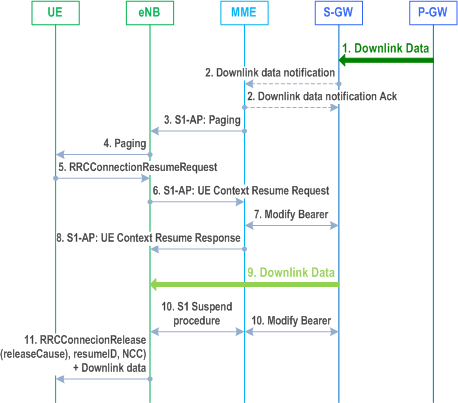
5.3.5B MT-EDT procedure for User Plane CIoT EPS Optimisation
5.3.6A PDN GW Pause of Charging procedure
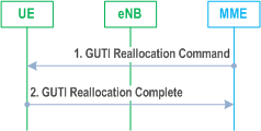
5.3.7 GUTI Reallocation procedure
...
...
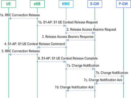
5.3.5 S1 release procedure p. 232
This procedure is used to release the logical S1-AP signalling connection (over S1-MME) and all S1 bearers (in S1-U) for a UE. This Procedure releases the S11-U bearer in Control Plane CIoT EPS Optimisation (except in the case of buffering in MME), instead of the S1-U bearer. The procedure will move the UE from ECM-CONNECTED to ECM-IDLE in both the UE and MME, and all UE related context information is deleted in the eNodeB. When the S1-AP signalling connection is lost, e.g. due to loss of the signalling transport or because of an eNodeB or MME failure, the S1 release procedure is performed locally by the eNodeB and by the MME. When the S1 release procedure is performed locally by the eNodeB or by the MME each node performs locally its actions as described in the procedure flow below without using or relying on any of the signalling shown directly between eNodeB and MME.
If Service Gap Control shall be applied for the UE (see clause 4.3.17.9) and the Service Gap timer is not already running, the Service Gap timer shall be started in MME and UE when entering ECM-IDLE, unless the connection was initiated after a paging of an MT event, or after a TAU procedure without any active flag set or signalling active flag set.
The initiation of S1 Release procedure is either:
- eNodeB-initiated with cause e.g. O&M Intervention, Unspecified Failure, User Inactivity, Repeated RRC signalling Integrity Check Failure, Release due to UE generated signalling connection release, CS Fallback triggered, Inter-RAT Redirection, UE using satellite access moved out of PLMN serving area, etc. as defined in TS 36.413; or
- MME-initiated with cause e.g. authentication failure, detach, not allowed CSG cell (e.g. the CSG ID of the currently used CSG cell expires or is removed from the CSG subscription data), etc.
Step 1a.
In certain cases the eNodeB may release the UE's signalling connection before or in parallel to requesting the MME to release the S1 context, e.g. the eNodeB initiates an RRC Connection Release for CS Fallback by redirection. If the reason for the release is that the eNodeB received Release Assistance Indicator in Access Stratum as defined in TS 36.321, the eNodeB should not immediately release the RRC connection, instead send S1 UE context Release Request with appropriate cause value e.g. user inactivity.
Step 1b.
Step 2.
Step 3.
Step 4.
Step 5.
Step 6.
Step 7.
Step 1b.
If the eNodeB detects a need to release the UE's signalling connection and all radio bearers for the UE, the eNodeB sends an S1 UE Context Release Request (Cause) message to the MME. Cause indicates the reason for the release (e.g. O&M intervention, unspecified failure, user inactivity, repeated integrity checking failure, or release due to UE generated signalling connection release).
If the PLMN has configured secondary RAT reporting and the eNodeB has Secondary RAT usage data to report, the Secondary RAT usage data is included in S1 UE Context Release Request.
The MME upon receiving S1 UE Context Release Request with Cause=user inactivity continues with the S1 release procedure unless the MME is aware of pending MT traffic or signalling and/or NAS Release Assistance Information that may have been received in NAS PDU when Control Plane CIoT EPS Optimisation is used, which indicates that downlink data is expected.
The MME upon receiving S1 UE Context Release Request with Cause indicating the release is requested due to a UE using satellite access moved out of PLMN serving area, may detach the UE as described in clause 5.3.8.3 before continuing with the S1 Release procedure.
For Control Plane CIoT EPS Optimisation with data buffering in the MME, step 2 and step 3 are skipped.
Step 2.
The MME sends a Release Access Bearers Request (Abnormal Release of Radio Link Indication, Secondary RAT usage data) message to the S-GW that requests the release of all S1-U bearers for the UE, or the S11-U in Control Plane CIoT EPS Optimisation if buffering is in the S-GW. This message is triggered either by an S1 Release Request message from the eNodeB, or by another MME event. The Abnormal Release of Radio Link Indication is included if the S1 release procedure is due to an abnormal release of the radio link. If secondary RAT usage data was received in Step 1b, the MME includes Secondary RAT usage data in this message.
Step 3.
If the S-GW has received a Release Access Bearers Request, the S-GW releases all eNodeB related information (address and TEIDs), or the MME TEIDs related information in Control Plane CIoT EPS Optimisation (address and TEIDs), for the UE and responds with a Release Access Bearers Response message to the MME. Other elements of the UE's S-GW context are not affected. The S-GW retains the S1-U configuration that the S-GW allocated for the UE's bearers. The S-GW starts buffering downlink packets received for the UE and initiating the "Network Triggered Service Request" procedure, described in clause 5.3.4.3, if downlink packets arrive for the UE. In Control Plane CIoT EPS Optimisation Downlink data triggers Mobile Terminated Data transport in NAS signalling defined in clause 5.3.4B.3.
Step 4.
The MME releases S1 by sending the S1 UE Context Release Command (Cause) message to the eNodeB.
Step 5.
If the RRC connection is not already released, the eNodeB sends a RRC Connection Release message to the UE in Acknowledged Mode. Once the message is acknowledged by the UE, the eNodeB deletes the UE's context.
Step 6.
The eNodeB confirms the S1 Release by returning an S1 UE Context Release Complete (ECGI, TAI, Secondary RAT usage data) message to the MME. With this, the signalling connection between the MME and the eNodeB for that UE is released. This step shall be performed promptly after step 4, e.g. it shall not be delayed in situations where the UE does not acknowledge the RRC Connection Release.
If Dual Connectivity was activated by that eNodeB at the time of the release or earlier by that eNodeB, the eNodeB shall include the last known PSCell ID and the time elapsed since the Dual Connectivity was released.
If the eNodeB supports WUS, the eNodeB should include the Information On Recommended Cells And eNodeBs For Paging in the S1 UE Context Release Complete message; otherwise, the eNodeB may include the Information On Recommended Cells And eNodeBs For Paging in the S1 UE Context Release Complete message. If available, the MME shall store this information to be used when paging the UE.
The eNodeB includes Information for Enhanced Coverage, if available, in the S1 UE Context Release Complete message.
If the PLMN has configured secondary RAT usage data reporting, the eNodeB has not included Secondary RAT usage data at step 1b, and the eNodeB has Secondary RAT usage data to report, the Secondary RAT usage data is included in this message. If Secondary RAT usage data was included at step 1b then MME ignores Secondary RAT usage data at step 6.
The MME deletes any eNodeB related information ("eNodeB Address in Use for S1-MME", "MME UE S1 AP ID" and "eNodeB UE S1AP ID") from the UE's MME context, but, retains the rest of the UE's MME context including the S-GW's S1-U configuration information (address and TEIDs). All non-GBR EPS bearers established for the UE are preserved in the MME and in the Serving-GW.
If the cause of S1 release is because of User I inactivity, Inter-RAT Redirection, the MME shall preserve the GBR bearers. If the cause of S1 release is because of CS Fallback triggered, further details about bearer handling are described in TS 23.272. Otherwise, e.g. Radio Connection With UE Lost, S1 signalling connection lost, eNodeB failure the MME shall trigger the MME Initiated Dedicated Bearer Deactivation procedure (clause 5.4.4.2) for the GBR bearer(s) of the UE after the S1 Release procedure is completed.
If LIPA is active for a PDN connection, the HeNB informs the collocated L-GW by internal signalling to releases the direct user plane path to the HeNB. After the direct user plane path is released, if downlink packets arrive for the UE, the L-GW forwards the first packet on the S5 tunnel to the S-GW to initiate the "Network Triggered Service Request" procedure, as described in clause 5.3.4.3.
Step 7.
If the eNodeB provided and MME accepted Secondary RAT usage data in step 6 (i.e. MME initiated S1 release), the MME initiates the Secondary RAT usage data reporting procedure in clause 5.7A.3 as illustrated in Figure 5.7A.3-2 (steps 7a - 7d). If PGW secondary RAT usage reporting is active, steps 7b and 7c are performed, otherwise only steps 7a and 7d are performed.
If the eNodeB provided Secondary RAT usage data in step 1b (i.e. eNodeB initiated S1 release) and PGW secondary RAT usage data reporting is active, the MME initiates the Secondary RAT usage data reporting procedure in clause 5.7A.3 as illustrated in Figure 5.7A.3-2.
5.3.5A Connection Resume procedure |R13| p. 234
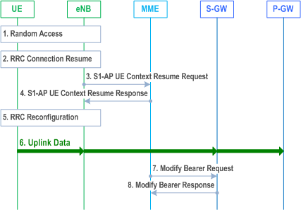
This procedure is used by the UE to resume the ECM-connection if the UE and the network support User Plane CIoT EPS Optimisation and the UE has stored the necessary information to conduct the Connection Resume procedure (see TS 36.300) otherwise the Service Request procedures are used, see clause 5.3.4.
Step 1.
Step 2.
Step 3.
Step 3a.
Step 3b.
Step 3c.
Step 4.
Step 5.
Step 6.
Step 7.
Step 8.
The UE triggers the Random Access procedure to the eNodeB, see TS 36.300.
Step 2.
The UE triggers the RRC Connection Resume procedure including information needed by the eNodeB to access the UE's stored AS context, see TS 36.300. The E-UTRAN performs security checks. EPS bearer state synchronization is performed between the UE and the network, i.e. the UE shall locally remove any EPS bearer for which no radio bearer is setup and which is not a Control Plane CIoT EPS bearer. If the radio bearer for a default EPS bearer is not established, the UE shall locally deactivate all EPS bearers associated to that default EPS bearer.
Step 3.
The eNodeB notifies the MME that the UE's RRC connection is resumed in the S1-AP UE Context Resume Request message which includes an RRC resume cause. If the eNodeB is not able to admit all suspended bearers, the eNodeB shall indicate this in the list of rejected EPS bearers, see TS 36.413.
When the UE attempts to establish a signalling connection and the following conditions are met:
- the eNodeB serves more than one country (e.g. it supports E-UTRA satellite access); and
- the eNodeB knows in what country the UE is located; and
- the eNodeB is connected to MMEs serving different PLMNs of different countries; and
- the UE provides an S-TMSI or GUMMEI, which indicates an MME serving a different country to where the UE is currently located; and
- the eNodeB is configured to enforce selection of the MME based on the country the UE is currently located;
Step 3a.
If the S1-U connection is resumed and the UE is accessing via the NB-IoT RAT with the RRC resume cause set to "MO exception data", the MME should notify the Serving Gateway of each use of this establishment cause by the MO Exception Data Counter. The MME maintains the MO Exception Data Counter and sends it to the Serving-GW as indicated in TS 29.274.
Step 3b.
The Serving Gateway should notify the PDN-GW if the RRC establishment cause "MO Exception Data" has been used by the MO Exception Data Counter (see TS 29.274). The Serving-GW indicates each use of this RRC establishment cause by the related counter on its CDR.
Step 3c.
The PDN-GW indicates each use of the RRC establishment cause "MO Exception Data" by the related counter on its CDR.
Step 4.
MME acknowledges the connection resumption in S1-AP UE Context Resume Response message. If the MME is not able to admit all suspended E-RABs the MME shall indicate this in the E-RABs Failed To Resume List IE.
Step 5.
If the MME included in step 4 a list of E-RABs failed to resume, the eNodeB reconfigures the radio bearers.
Step 6.
The uplink data from the UE can now be forwarded by eNodeB to the Serving-GW. The eNodeB sends the uplink data to the Serving-GW address and TEID stored during the Connection Suspend procedure, see clause 5.3.4A. The Serving-GW forwards the uplink data to the PDN-GW.
Step 7.
The MME sends a Modify Bearer Request message (eNodeB address, S1 TEID(s) (DL) for the accepted EPS bearers, Delay Downlink Packet Notification Request, RAT Type) per PDN connection to the Serving-GW. If the Serving-GW supports Modify Access Bearers Request procedure and if there is no need for the Serving-GW to send the signalling to the PDN-GW, the MME may send Modify Access Bearers Request (eNodeB address(es) and TEIDs for downlink user plane for the accepted EPS bearers, Delay Downlink Packet Notification Request) per UE to the Serving-GW to optimise the signalling. The Serving-GW is now able to transmit downlink data towards the UE.
The MME and the Serving-GW clears the DL Data Buffer Expiration Time in their UE contexts if it was set, to remember that any DL data buffered for a UE using power saving functions has been delivered and to avoid any unnecessary user plane setup in conjunction with a later TAU.
Step 8.
The Serving-GW shall return a Modify Bearer Response (Serving-GW address and TEID for uplink traffic) to the MME as a response to a Modify Bearer Request message, or a Modify Access Bearers Response (Serving-GW address and TEID for uplink traffic) as a response to a Modify Access Bearers Request message. If the Serving-GW cannot serve the MME Request in the Modify Access Bearers Request message without S5/S8 signalling other than to unpause charging in the PDN-GW or without corresponding Gxc signalling when PMIP is used over the S5/S8 interface, it shall respond to the MME with indicating that the modifications are not limited to S1-U bearers, and the MME shall repeat its request using a Modify Bearer Request message per PDN connection.
If SIPTO at the Local Network is active for a PDN connection with stand-alone GW deployment and the Local Home Network ID for stand-alone accessed by the UE differs from the Local Home Network ID where the UE initiated the SIPTO@LN PDN Connection, the MME shall request disconnection of the SIPTO at the local network PDN connection(s) with the "reactivation requested" cause value according to clause 5.10.3. If the UE has no other PDN connection, the MME initiated "explicit detach with reattach required" procedure according to clause 5.3.8.3.
If SIPTO at the Local Network is active for a PDN connection with collocated LGW deployement and the L-GW CN address of the cell accessed by the UE differs from the L-GW CN address of the cell where the UE initiated the SIPTO at the Local Network PDN Connection, the MME shall request disconnection of the SIPTO at the local network PDN connection(s) with the "reactivation requested" cause value according to clause 5.10.3. If the UE has no other PDN connection, the MME initiated "explicit detach with reattach required" procedure according to clause 5.3.8.3.
5.3.5B MT-EDT procedure for User Plane CIoT EPS Optimisation |R16| p. 236
Step 1.
Same as step 1 in clause 5.3.4.3.
Step 2.
Same as step 2 in clause 5.3.4.3, with the following addition:;
The Serving-GW may send the downlink data size to the MME for MT-EDT consideration if the downlink data is applicable for User Plane CIoT EPS Optimisation and MT-EDT is applicable for this PDN connection.
Step 3.
Same as step 3 in clause 5.3.4.3, with the following addition;
If MT-EDT is applicable for the PDN Connection, the MME may include the downlink data size in the Paging message to assist eNodeB to use MT-EDT.
Step 4.
Same as step 4 in cluse 5.3.4.3, with the following addition;
If data size is included in Paging message from MME, the eNodeB may decide to use MT-EDT, by adding a MT-EDT indication in the Paging message to the UE.
Step 5-8.
Follow the procedure as defined in clause 7.3b.3 in TS 36.300.
Step 9.
SGW delivers downlink data to RAN.
Step 10-11.
The eNodeB can decide to use MT-EDT and move the UE to IDLE mode.
5.3.6 Void
5.3.6A PDN GW Pause of Charging procedure |R12| p. 237
The PDN-GW Pause of Charging procedure is optionally supported by the Serving-GW and PDN-GW and has the purpose to limit a mismatch between PDN-GW and Serving-GW charging volume and packet counts. Generally, it aims for the PDN-GW charging and usage monitoring data to more accurately reflect the downlink traffic actually sent to the E-UTRAN.
The Serving-GW may indicate support of this function to the PDN-GW when the PDN connection is activated or when a new/target Serving-GW is used for a PDN connection. This is indicated to the PDN-GW by a "PDN Charging Pause Support Indication" in the Create Session Request during PDN activation/Attach and in the Modify Bearer Request in procedures with a change of Serving-GW.
The PDN-GW may indicate if the feature is to be enabled on a per PDN connection basis, if the current Serving-GW supports the feature and the operator's policy is to enable the feature. This is indicated to the Serving-GW by a "PDN Charging Pause Enabled" Indication in the Create Session Response during PDN activation/Attach and in the Modify Bearer Response in procedures with a change of Serving-GW. This is an indication to the Serving-GW that when the criteria for pause of PDN-GW charging are met (as described further down in this clause) the PDN-GW charging can be paused.
The PDN-GW shall stop any charging and usage monitoring actions for the PDN connection upon receiving a "PDN Charging Pause Start" Indication in a Modify Bearer Request. When the PDN-GW receives a Modify Bearer Request for a PDN connection for which charging has been stopped previously and, if the Modify Bearer Request contains a "PDN Charging Pause Stop" Indication or does not contain a "PDN Charging Pause Start" Indication, then the PDN-GW shall continue charging for the PDN connection.
When bearers become suspended for a UE (see TS 23.272), the PDN-GW charging is no longer paused and the PDN-GW continues charging for the PDN connection after suspended bearers are resumed.
While the PDN-GW charging is currently paused and the UE is in ECM-IDLE (for ISR case the device is at same time in PMM-IDLE or STANDBY in UTRAN/GERAN accesses) the following applies:
- The PDN-GW shall not perform charging and usage monitoring actions for downlink traffic on this PDN.
- Based on operator policy/configuration in the PDN-GW, the PDN-GW may limit the rate of downlink traffic sent to the Serving-GW.
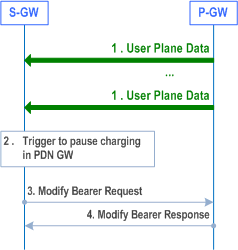
Step 1.
The Serving-GW receives downlink data packets for a UE known as not user plane connected (i.e. the Serving-GW context data indicates no downlink user plane TEID for the eNodeB) as described in clause 5.3.4.3 step 1, i.e. the packets are buffered or discarded in Serving-GW based on operator policy.
Step 2.
Based on operator policy/configuration the Serving-GW triggers the procedure to pause PDN charging. Triggering criteria are based on Serving-GW operator policy/configuration. Example of such policy may be:
Step 3.
- Operator specified criteria/threshold (e.g. number/fraction of packets/bytes dropped at Serving-GW in downlink since last time the UE was in ECM-CONNECTED state (or for ISR case PMM-CONNECTED state)).
- Recent indication of "Abnormal Release of Radio Link" (see clause 5.3.5) or a recent Downlink Data Notification Reject (clause 5.3.4.3) without UE shortly re-entering ECM-CONNECTED state (or for ISR case without also re-entering PMM-CONNECTED state).
Serving-GW sends a Modify Bearer Request (PDN Charging Pause Start) message to the PDN-GW. PDN Charging Pause Start indicates that PDN-GW charging shall be paused.
Step 4.
PDN-GW confirms with a Modify Bearer Response message.
5.3.7 GUTI Reallocation procedure p. 239
The MME may initiate the GUTI Reallocation procedure to reallocate the GUTI and/or TAI list at any time when a signalling association is established between UE and MME. The GUTI Reallocation procedure allocates a new GUTI and/or a new TAI list and/or PLMN-assigned UE Radio Capability ID to the UE. The GUTI and/or the TAI list may also be reallocated by the Attach or the Tracking Area Update procedures.
When the UE supports RACS, and the MME needs to configure the UE with a UE Radio Capability ID, and the MME already has the UE radio capabilities for the UE, the MME may initiate the GUTI Reallocation procedure to provide the UE with the UE Radio Capability ID for the UE radio capabilities the UCMF returns to the MME for this UE. When the UE supports RACS, and the MME needs to delete any previously assigned PLMN-assigned UE Radio Capability ID(s) for the UE, the MME may initiate the GUTI Reallocation procedure to signal a PLMN-assigned UE Radio Capability ID deletion indication. If the UE receives PLMN-assigned UE Radio Capability ID deletion indication, the UE shall delete any PLMN-assigned UE Radio Capability ID(s) for this PLMN.
The GUTI Reallocation procedure is illustrated in Figure 5.3.7-1.
