Content for TS 22.261 Word version: 20.1.0
0…
4…
6…
6.4…
6.8…
6.12…
6.15…
6.16…
6.22…
6.26…
6.30…
6.37…
6.41…
6.43…
6.46…
7…
7.4…
7.9
7.10…
7.11…
8…
D…
D.3…
F…
G…
H
I
J…
D Critical-communication use cases
D.1 Factory automation - motion control
D.1.0 General
D.1.1 Service area and connection density
D.1.2 Security
D.2 Factory automation - other use cases
D.2.0 General
D.2.1 Service area and connection density
D.2.2 Security
...
...
D Critical-communication use cases p. 120
D.1 Factory automation - motion control p. 120
D.1.0 General |R18| p. 120
Factory automation requires communications for closed-loop control applications. Examples for such applications are motion control of robots, machine tools, as well as packaging and printing machines. All other factory automation applications are addressed in Annex D.2.
The corresponding industrial communication solutions are referred to as fieldbuses. The pertinent standard suite is IEC 61158. Note that clock synchronization is an integral part of fieldbuses that support motion control use cases.
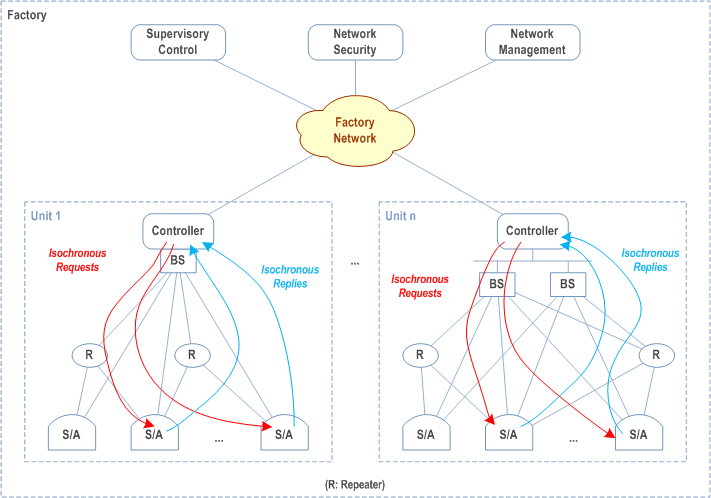
In motion control applications, a controller interacts with a large number of sensors and actuators (e.g. up to 100) that are integrated in a manufacturing unit. The resulting sensor/actuator density is often very high (up to 1 m-3). Many such manufacturing units have to be supported within close proximity within a factory (e.g. up to 100 in automobile assembly line production).
In a closed-loop control application, the controller periodically submits instructions to a set of sensor/actuator devices, which return a response within a so-called cycle time. The messages, which are referred to as telegrams, are typically small (≤ 56 bytes). The cycle time can be as low as 2 ms, setting stringent end-to-end latency constraints on telegram forwarding (≤ 1 ms). Additional constraints on isochronous telegram delivery add tight constraints on the lateness (1 μs), and the communication service has also to be highly available (99.999 9%).
Multi-robot cooperation is a case in closed-loop control, where a group of robots collaborate to conduct an action, for example, symmetrical welding of a car body to minimize deformation. This requires isochronous operation between all robots. For multi-robot cooperation, the lateness (1 μs) is to be interpreted as the lateness among the command messages of a control event to the group robots.
To meet the stringent requirements of closed-loop factory automation, the following considerations have to be taken:
- Limitation to short-range communications.
- Use of direct device connection between the controller and actuators.
- Allocation of licensed spectrum. Licensed spectrum can further be used as a complement to unlicensed spectrum, e.g. to enhance reliability.
- Reservation of dedicated radio interface resources for each link.
- Combination of multiple diversity techniques to approach the high reliability target within stringent end-to-end latency constraints (example: frequency, antenna and various forms of spatial diversity, e.g. via relaying)
- Utilizing OTA time synchronization to satisfy latency-variation constraints for isochronous operation.

Figure D.1.0-1 depicts how communication can occur in factory automation. In this use case, communication is confined to local controller-to-sensor/actuator interaction within each manufacturing unit. Repeaters can provide spatial diversity to enhance reliability.
D.1.1 Service area and connection density p. 121
The maximum service volume in motion control is currently set by hoisting solutions, i.e. cranes, and by the manipulation of large machine components, e.g. propeller blades of wind-energy generators. Cranes can be rather wide and quite high above the shop floor, even within a factory hall. In addition, they typically travel along an entire factory hall.
An approximate dimension of the service area is 100 x 100 x 30 m.
Note that production cells are commonly much smaller (< 10 x 10 x 3 m). There are typically about 10 motion-control connections in a production cell, which results in a connection density of up to 105 km-2.
D.1.2 Security p. 121
Network access and authorization in an industrial factory deployment is typically provided and managed by the factory owner with its ID management, authentication, confidentiality and integrity.
Note that motion control telegrams usually are not encrypted due to stringent cycle time requirements.
A comprehensive security framework for factories has been described in IEC 62443.
D.2 Factory automation - other use cases p. 122
D.2.0 General |R18| p. 122
Factory automation encompasses all types of production that result in discrete products: cars, chocolate bars, etc. Automation that addresses the control of flows and chemical reactions is referred to as process automation (see clause D.3). Discrete automation requires communications for supervisory and open-loop control applications, as well as process monitoring and tracking of operations inside an industrial plant. In these applications, a large number of sensors, which are distributed over the plant, forward measurement data to process controllers on a periodic or event-driven base. Traditionally, wireline field bus technologies have been used to interconnect sensors and control equipment. Due to the sizable extension of a plant (up to 10 km²), the large number of sensors, rotary joints, and the high deployment complexity of wired infrastructure, wireless solutions have made inroads into industrial process automation.
The related use cases require support of a large number of sensor devices per plant as well as high communication service availability (99.99%). Furthermore, power consumption is relevant since some sensor devices are battery-powered with a targeted battery lifetime of several years (while providing measurement updates every few seconds). Range also becomes a critical factor due to the low transmit power levels of the sensors, the large size of the plant, and the high-reliability requirements on transport. End-to-end latency requirements typically range between 10 ms and 1 s. User-experienced data rates can be rather low since each transaction typically comprises less than 256 bytes. However, there has been a shift from field busses featuring somewhat modest data rates (~ 2 Mbit/s) to those with higher data rates (~ 10 Mbit/s) due to the increasing number of distributed applications and also "data-hungry" applications. An example for the latter is the visual control of production processes. For this application, the user experienced data rate is typically around 10 Mbit/s and the transmitted packets are much larger than what was stated earlier.
Existing wireless technologies for factory automation rely on unlicensed bands. Communication is therefore vulnerable to interference caused by other technologies (e.g. WLAN). With the stringent requirements on transport reliability, such interference is detrimental to proper operation.
The use of licensed spectrum could overcome the vulnerability to same-band interference and therefore enable higher reliability. Utilization of licensed spectrum can be confined to those events where high interference bursts in unlicensed bands jeopardizes communication service availability and end-to-end latency constraints. This allows sharing the licensed spectrum between process automation and conventional mobile services.
Multi-hop topologies can provide range extension and mesh topologies can increase reliability through path redundancy. Clock synchronization will be highly beneficial since it enables more power-efficient sensor operation and mesh forwarding.
The corresponding industrial communication solutions are referred to as fieldbuses. The related standard suite is IEC 61158.
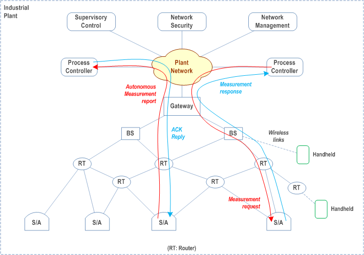
A typical discrete automation application supports downstream and upstream data flows between process controllers and sensors/actuators. The communication consists of individual transactions. The process controller resides in the plant network. This network interconnects via base stations to the wireless (mesh-) network which hosts the sensor/actuator devices. Typically, each transaction uses less than 256 bytes. An example of a controller-initiated transaction service flow is:
- The process controller requests sensor data (or an actuator to conduct actuation). The request is forwarded via the plant network and the wireless network to the sensors/actuators.
- The sensors/actuators process the request and send a replay in upstream direction to the controller. This reply can contain an acknowledgement or a measurement reading.
- The sensor sends a measurement reading to the process controller. The request is forwarded via the wireless (mesh) network and the plant network.
- The process controller can send an acknowledgement in opposite direction. For both controller- and sensor/actuator-initiated service flows, upstream and downstream transactions can occur asynchronously.

D.2.1 Service area and connection density p. 123
Factory halls can be rather large and even quite high. We set the upper limit at 1000 x 1000 x 30 m. Note that the connection density might vary quite a bit throughout factory halls. The density is, for instance, much higher along an assembly line than in an overflow buffer. Also, the density usually increases towards the factory floor. Typically, there is at least one connection per 10 m², which results in a connection density of up to 105 km².
D.2.2 Security p. 123
Network access and authorization in an industrial factory deployment is typically provided and managed by the factory owner with its ID management, authentication, confidentiality and integrity.
A comprehensive security framework for factories has been described in IEC 62443.