Content for TS 38.305 Word version: 18.3.0
1…
4…
5…
6…
6.5…
6.7…
7…
7.3A…
7.4…
7.6…
7.11…
7.12…
8…
8.1.2.1a…
8.1.3…
8.2…
8.3…
8.4…
8.5…
8.6…
8.7…
8.8…
8.9…
8.10…
8.11…
8.12…
8.13…
8.14…
8.15…
A…
8.10 Multi-RTT positioning
8.10.1 General
8.10.2 Information to be transferred between NG-RAN/5GC Elements
8.10.2.0 General
8.10.2.1 Information that may be transferred from the LMF to UE
8.10.2.2 Information that may be transferred from the UE to LMF
8.10.2.3 Information that may be transferred from the gNB to LMF
8.10.2.4 Information that may be transferred from the LMF to gNBs
8.10.3 Multi-RTT Positioning Procedures
8.10.3.0 General
8.10.3.1 Procedures between LMF and UE
8.10.3.1.1 Capability Transfer Procedure
8.10.3.1.2 Assistance Data Transfer Procedure
8.10.3.1.2.1 Assistance Data Transfer between LMF and UE
8.10.3.1.2.1.0 General
8.10.3.1.2.1.1 LMF initiated Assistance Data Delivery
8.10.3.1.2.1.2 UE initiated Assistance Data Transfer
8.10.3.1.3 Location Information Transfer Procedure
8.10.3.1.3.0 General
8.10.3.1.3.1 LMF-initiated Location Information Transfer Procedure
8.10.3.1.3.2 UE-initiated Location Information Delivery procedure
8.10.3.2 Procedures between LMF and gNB
8.10.3.2.1 Assistance Data Delivery between LMF and gNB
8.10.3.2.2 Location Information Transfer/Assistance Data Transfer Procedure
8.10.3.2.3 Positioning Activation/Deactivation Procedure
8.10.4 Sequence of Procedure for Multi-RTT positioning
...
...
8.10 Multi-RTT positioning |R16| p. 126
8.10.1 General p. 126
In the Multi-RTT positioning method, the UE position is estimated based on measurements performed at both, UE and TRPs. The measurements performed at the UE and TRPs are UE/gNB Rx-Tx time difference measurements (and optionally DL-PRS-RSRP, DL-PRS-RSRPP, UL-SRS-RSRP, UL-SRS-RSRPP, and/or DL-RSCP/UL-RSCP) of DL-PRS and UL-SRS, which are used by an LMF to determine the RTTs.
For network verification of UE location in NTN, the measurements can be performed at a single TRP at different time instances. The additional measurements performed at UE are the UE Rx - Tx time difference subframe offset in unit of subframe and the DL timing drift due to Doppler in service link between UE and satellite as defined in TS 38.215.
The UE may require measurement gaps to perform the Multi-RTT measurements from NR TRPs. The UE may request measurement gaps from a gNB using the procedure described in clause 7.4.1.1. The UE may also request to activate pre-configured measurement gaps as described in clause 7.7.2.
8.10.2 Information to be transferred between NG-RAN/5GC Elements p. 126
8.10.2.0 General |R18| p. 126
This clause defines the information that may be transferred between LMF and UE/gNB.
8.10.2.1 Information that may be transferred from the LMF to UE p. 126
The information that may be transferred from the LMF to the UE are listed in Table 8.10.2.1-1.
| Information |
|---|
| Physical cell IDs (PCIs), global cell IDs (GCIs), and PRS IDs, ARFCNs of candidate NR TRPs for measurement |
| Timing relative to the serving (reference) TRP of candidate NR TRPs |
| DL-PRS configuration of candidate NR TRPs |
| Indication of which DL-PRS Resource Sets across DL-PRS positioning frequency layers are linked for DL-PRS bandwidth aggregation |
| SSB information of the TRPs (the time/frequency occupancy of SSBs) |
| PRS-only TP indication |
| On-Demand DL-PRS-Configurations, possibly together with information on which configurations are available for DL-PRS bandwidth aggregation |
| Validity Area of the Assistance Data |
8.10.2.2 Information that may be transferred from the UE to LMF p. 127
The information that may be signalled from UE to the LMF is listed in Table 8.10.2.2-1. The individual UE measurements are defined in TS 38.215.
| Information |
|---|
| PCI, GCI, and PRS ID, ARFCN, PRS resource ID, PRS resource set ID for each measurement |
| DL-PRS-RSRP measurement |
| UE Rx-Tx time difference measurement |
| DL-RSCP measurementNOTE1, NOTE 2 |
| Time stamp of the measurement |
| Quality for each measurement |
| TA offset used by UE |
| UE Rx TEG IDs, UE Tx TEG IDs, and UE RxTx TEG IDs associated with UE Rx-Tx time difference measurements |
| LOS/NLOS information for UE measurements |
| DL-PRS-RSRPP measurement |
| The association of UE Tx TEG ID and SRS |
| Indication that DL-PRS bandwidth aggregation has been used for UE Rx-Tx time difference measurement |
| Indication that the reported measurements are based on receiving single or multiple hops of DL-PRS |
| UE Rx - Tx time difference subframe offset |
| DL timing drift |
|
NOTE 1:
The DL-RSCP measurement may be reported along with the UE Rx-Tx time difference measurement.
NOTE 2:
The DL-RSCP is measured from a single DL PRS positioning frequency layer.
|
8.10.2.3 Information that may be transferred from the gNB to LMF p. 127
The assistance data that may be transferred from gNB to the LMF is listed in Table 8.10.2.3-1.
| Information |
|---|
| PCI, GCI, ARFCN and TRP IDs of the TRPs served by the gNB |
| Timing information of TRPs served by the gNB |
| DL-PRS configuration of the TRPs served by the gNB |
| Indication of which DL-PRS Resource Sets across DL-PRS positioning frequency layers are linked for DL-PRS bandwidth aggregation |
| SSB information of the TRPs (the time/frequency occupancy of SSBs) |
| Spatial direction information of the DL-PRS Resources of the TRPs served by the gNB |
| Geographical coordinates information of the DL-PRS Resources of the TRPs served by the gNB |
| TRP type |
| On-demand DL-PRS information, possibly together with information on which configurations are available for DL-PRS bandwidth aggregation |
| TRP Tx TEG association information |
| Common TA parameters of TRPs |
| Mobile TRP Location Information |
| Mobile IAB-MT UE ID (NOTE 1) |
|
NOTE 1:
If TRP Type is Mobile TRP.
|
The configuration data for a target UE that may be transferred from the serving gNB to the LMF is listed in Table 8.10.2.3-2.
| UE configuration data |
|---|
| UE SRS configuration |
| SFN initialization time for the SRS configuration |
| SRS Transmission Status |
| Positioning validity area cell list |
| SRS preconfiguration list |
| New NR CGI |
The measurement results that may be signalled from gNBs to the LMF is listed in Table 8.10.2.3-3.
| Measurement results |
|---|
| NCGI and TRP ID of the measurement |
| gNB Rx-Tx time difference measurement |
| UL-SRS-RSRP |
| UL-SRS-RSRPP |
| UL-RSCP measurement |
| UL Angle of Arrival (azimuth and/or elevation) NOTE 1 |
| Multiple UL Angle of Arrival (azimuth and/or elevation) NOTE 1 |
| SRS Resource Type |
| Time stamp of the measurement |
| Quality for each measurement |
| Beam Information of the measurement |
| LoS/NLoS information for each measurement |
| ARP ID of the measurement |
| Mobile TRP Location Information |
| Measured frequency hops |
| Aggregated positioning SRS resource ID list |
| Measurement based on aggregated resources indication |
|
NOTE 1:
When used with UL-AoA for hybrid positioning.
|
8.10.2.4 Information that may be transferred from the LMF to gNBs p. 128
The requested UL-SRS transmission characteristics information that may be signalled from the LMF to the gNB is listed in Table 8.10.2.4-1.
| Information |
|---|
| Number Of Transmissions/duration for which the UL-SRS is requested |
| Bandwidth |
| Resource type (periodic, semi-persistent, aperiodic) |
| Number of requested SRS resource sets and SRS resources per set |
Pathloss reference:
|
Spatial relation info
|
| Periodicity of the SRS for each SRS resource set |
| SSB Information |
| Carrier frequency of SRS transmission bandwidth |
| Bandwidth aggregation request indication |
| Positioning validity area cell list |
| Validity area specific SRS information |
The TRP measurement request information that may be signalled from the LMF to the gNBs is listed in Table 8.10.2.4-2.
| Information |
|---|
| TRP ID, and NCGI of the TRP to receive UL-SRS |
| UE-SRS configuration |
| UL timing information together with timing uncertainty, for reception of SRS by candidate TRPs |
| Report characteristics for the measurements |
| Measurement Quantities |
| Measurement periodicity and amount |
| Measurement beam information request |
| Search window information |
| Expected UL AoA/ZoA and uncertainty range |
| Number of TRP Rx TEGs |
| Number of TRP RxTx TEGs |
| Response time |
| Measurement characteristics request indicator |
| Measurement time occasions for a measurement instance |
| Time window information for measurements |
The Positioning Activation/Deactivation request information that may be signalled from the LMF to the gNB is listed in Table 8.10.2.4-3.
| Information |
|---|
SP UL-SRS:
|
Aperiodic UL-SRS
|
UL-SRS:
|
8.10.3 Multi-RTT Positioning Procedures p. 130
8.10.3.0 General |R18| p. 130
The procedures described in this clause support Multi-RTT positioning measurements obtained by the UE and TRPs/gNB.
8.10.3.1 Procedures between LMF and UE p. 130
8.10.3.1.1 Capability Transfer Procedure p. 130
The Capability Transfer procedure for Multi-RTT positioning is described in clause 7.1.2.1.
8.10.3.1.2 Assistance Data Transfer Procedure p. 130
8.10.3.1.2.1 Assistance Data Transfer between LMF and UE p. 130
The purpose of this procedure is to enable the LMF to provide assistance data to the UE (e.g., as part of a positioning procedure) and the UE to request assistance data from the LMF (e.g., as part of a positioning procedure). The LMF may provide the pre-configured DL-PRS assistance data (with associated validity criteria) to the UE (before or during an ongoing LPP positioning session), to be utilized for potential positioning measurements at a future time. Pre-configured DL-PRS assistance data may consist of multiple instances, where each instance is applicable to a different area within the network. One or more assistance data instances may be provided. Each instance is provided in one LPP Assistance Data messages.
If a UE receives assistance data for a TRP for which it has already stored assistance data, it overwrites the stored assistance data, whereas if a UE receives assistance data for a TRP for which it has not stored assistance data, it stores the assistance data for the TRP and maintains the already stored assistance data for other TRPs. The TRPs are uniquely identified using a combination of PRS-ID and Cell-ID. The number TRPs for which the UE can store Assistance Data is a UE capability and is indicated by the number of areas a UE can support.
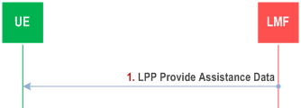
Figure 8.10.3.1.2.1.1-1 shows the Assistance Data Delivery operations for the Multi-RTT positioning method when the procedure is initiated by the LMF.
Step 1.
The LMF determines that assistance data needs to be provided to the UE (e.g., as part of a positioning procedure) and sends an LPP Provide Assistance Data message to the UE. This message may include any of the Multi-RTT positioning assistance data defined in Table 8.10.2.1-1.
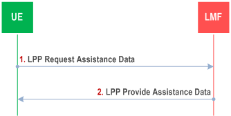
Figure 8.10.3.1.2.1.2-1 shows the Assistance Data Transfer operations for the Multi-RTT positioning method when the procedure is initiated by the UE.
Step 1.
The UE determines that certain Multi-RTT positioning assistance data are desired (e.g., as part of a positioning procedure when the LMF provided assistance data are not sufficient for the UE to fulfil the request) and sends an LPP Request Assistance Data message to the LMF. This request includes an indication of which specific Multi-RTT assistance data are requested. Additional information concerning the UE's approximate location and serving and neighbour cells may also be provided in the Request Assistance Data message and/or in an accompanying Provide Location Information message to help the LMF provide appropriate assistance data. This additional data may include the UE's last known location if available, the cell IDs of the UE serving NG-RAN node and possibly neighbour NG-RAN nodes, as well as NR E-CID measurements.
Step 2.
The LMF provides the requested assistance in an LPP Provide Assistance Data message, if available at the LMF. If any of the UE requested assistance data in step (1) are not provided in step 2, the UE shall assume that the requested assistance data are not supported, or currently not available at the LMF. If none of the UE requested assistance data in step (1) can be provided by the LMF, return any information that can be provided in an LPP message of type Provide Assistance Data which includes a cause indication for the not provided assistance data.
8.10.3.1.3 Location Information Transfer Procedure p. 131
8.10.3.1.3.0 General p. 131
The purpose of this procedure is to enable the LMF to request position measurements from the UE, or to enable the UE to provide location measurements to the LMF for position calculation.
8.10.3.1.3.1 LMF-initiated Location Information Transfer Procedure p. 132
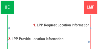
Figure 8.10.3.1.3.1-1 shows the Location Information Transfer operations for the Multi-RTT positioning method when the procedure is initiated by the LMF.
Step 1.
The LMF sends an LPP Request Location Information message to the UE. This request includes indication of Multi-RTT measurements requested, including any needed measurement configuration information, and required response time.
The LPP Request Location Information message may include one or more time windows during which the target device is requested to perform the Multi-RTT measurements on indicated DL-PRS Resource Sets.
The LPP Request Location Information message may include a request to perform joint UE Rx-Tx time difference measurement(s) across two or three DL-PRS positioning frequency layers.
The LPP Request Location Information message may include a request to perform the Multi-RTT measurements using receiver frequency hopping for a DL PRS resource within a configured measurement gap.
Step 2.
The UE obtains Multi-RTT measurements as requested in step 1. The UE then sends an LPP Provide Location Information message to the LMF, before the Response Time provided in step (1) elapsed, and includes the obtained Multi-RTT measurements. If the UE is unable to perform the requested measurements, or the Response Time elapsed before any of the requested measurements were obtained, the UE returns any information that can be provided in an LPP message of type Provide Location Information which includes a cause indication for the not provided location information.
8.10.3.1.3.2 UE-initiated Location Information Delivery procedure p. 132
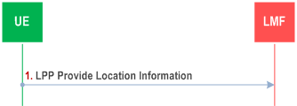
Figure 8.10.3.1.3.2-1 shows the Location Information Delivery procedure operations for the Multi-RTT positioning method when the procedure is initiated by the UE.
Step 1.
The UE sends an LPP Provide Location Information message to the LMF. The Provide Location Information message may include any UE Multi-RTT measurements already available at the UE.
8.10.3.2 Procedures between LMF and gNB p. 133
8.10.3.2.1 Assistance Data Delivery between LMF and gNB p. 133
The purpose of these procedures is to enable the gNB to provide assistance data described in Table 8.10.2.3-1 to the LMF, for subsequent delivery to the UE using the procedures of clause 8.10.3.1.2.1 or for use in the calculation of positioning estimates at the LMF or enable the LMF to request UL-SRS configuration information from the serving gNB of a target UE.
Figure 8.10.3.2.1-1 shows the TRP Information Exchange operation from the gNB to the LMF for the Multi-RTT positioning method.
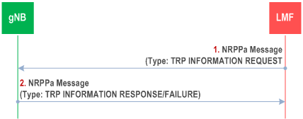
Step 1.
Figure 8.10.3.2.1-2 shows the UL information Delivery operation from the serving gNB to the LMF.
The LMF determines that certain TRP configuration information is desired (e.g., as part of a periodic update or as triggered by OAM) and sends an NRPPa TRP INFORMATION REQUEST message to the gNB. This request includes an indication of which specific TRP configuration information is requested.
Step 2.
The gNB provides the requested TRP information in an NRPPa TRP INFORMATION RESPONSE message, if available at the gNB. If the gNB is not able to provide any information, it returns an TRP INFORMATION FAILURE message indicating the cause of the failure.
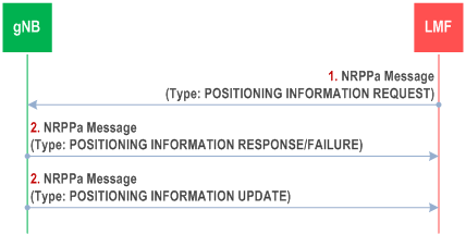
Step 1.
The LMF sends a NRPPa message POSITIONING INFORMATION REQUEST to the serving gNB of the target UE to request UE SRS configuration information. If the message includes the Requested UL-SRS Transmission Characteristics as listed in Table 8.10.2.4-1, the gNB should take this information into account when configuring UL-SRS transmissions for the UE.
Step 2.
The serving gNB determines the UE SRS configuration to be allocated for the UE and sends NRPPa message POSITIONING INFORMATION RESPONSE to the LMF that includes the UE SRS configuration defined in Table 8.10.2.3-2. If the serving gNB is not able to provide the requested information, it returns a failure message indicating the cause of the failure.
Step 3.
If a change has occurred in the UE SRS configuration during the UE SRS time duration requested at step 1, the gNB sends a POSITIONING INFORMATION UPDATE message to the LMF. This message contains, in the case of a change in UE SRS configuration parameters, the UE SRS configuration information for all cells with UE SRS configured, or an update in SRS transmission status.
8.10.3.2.2 Location Information Transfer/Assistance Data Transfer Procedure p. 134
The purpose of this procedure is to enable the LMF to request position measurements from a gNB for position calculation of the UE and also provide necessary assistance data to the gNB.
Figure 8.10.3.2.2-1 shows the messaging between the LMF and the gNB to perform this procedure.
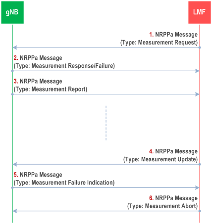
Step 1.
The LMF sends a NRPPa message to the selected gNB to request Multi-RTT measurement information. The message includes any information required for the gNB to perform the measurements as defined in Table 8.10.2.4-2.
Step 2.
If the report characteristics in step 1 is set to "on demand", the gNB obtains the requested Multi-RTT measurements and returns them in a Measurement Response message to the LMF. The Measurement Response message includes the obtained Multi-RTT measurements as defined in Table 8.10.2.3-3.
If the report characteristics in step 1 is set to "periodic", the gNB replies with a Measurement Response message without including any measurements in the message. The gNB then periodically initiates the Measurement Report procedure in step 3 for the Multi-RTT measurements, with the requested reporting periodicity.
If the gNB is not able to accept the Measurement Request message in step 1, the gNB returns a failure message indicating the cause of the failure.
Step 3.
The gNB periodically provides the Multi-RTT measurements as defined in Table 8.10.2.3-3 to the LMF if that was requested at step 1.
Step 4.
At any time after step 2, the LMF may send a Measurement Update message to the gNB providing updated information required for the gNB to perform the Multi-RTT measurements as defined in Table 8.10.2.4-2. Upon receiving the message, the gNB overwrites the previously received measurement configuration information.
Step 5.
If the previously requested Multi-RTT measurements can no longer be reported, the gNB notifies the LMF by sending a Measurement Failure Indication message.
Step 6.
When the LMF wants to abort an ongoing Multi-RTT measurement it sends a Measurement Abort message to the gNB.
8.10.3.2.3 Positioning Activation/Deactivation Procedure p. 135
The purpose of this procedure is to enable the LMF to request activation and deactivation of UL-SRS transmission of the target UE.
Figure 8.10.3.2.3-1 shows the messaging between the LMF and the gNB to perform this procedure.
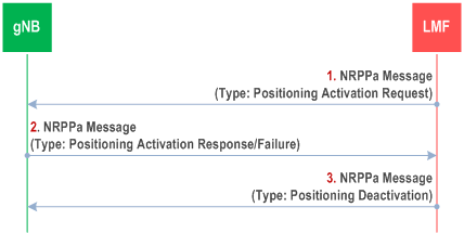
Step 1.
The LMF sends the NRPPa Positioning Activation Request message to the serving gNB of the target UE to request UL-SRS activation for the target UE. For a semi-persistent UL-SRS, the message includes an indication of an UL-SRS resource set to be activated and may include information that indicates the spatial relation for the semi-persistent UL-SRS resource to be activated, as listed in Table 8.10.2.4-3. For an aperiodic UL-SRS, the message may include aperiodic SRS Resource trigger list to indicate the UL-SRS resource to be activated.
Step 2.
For semi-persistent UL-SRS, the serving gNB may then activate the configured semi-persistent UL-SRS resource sets by sending the SP Positioning SRS Activation/Deactivation MAC CE command as specified in TS 38.321. For aperiodic UL-SRS, the serving gNB may then activate the configured aperiodic UL-SRS resource sets by sending the DCI as specified in TS 38.212.
If the UL-SRS has been successfully activated as requested in step 1, the gNB sends the NRPPa Positioning Activation Response message to the LMF. The serving gNB may include a system frame number and a slot number in the NRPPa Positioning Activation Response message to the LMF. If the serving gNB is not able to fulfil the request from step 1, it returns the Positioning Activation Failure message indicating the cause of the failure.
Step 3.
If a previously activated UL-SRS should be deactivated, or the UL-SRS transmission should be released, the LMF sends the NRPPa Positioning Deactivation message to the serving gNB of the target device to request deactivation of UL-SRS resource sets, or release all the UL-SRS resources. This message includes an indication of the UL-SRS resource set to be deactivated, or an indication of releasing all UL-SRS resources.
8.10.4 Sequence of Procedure for Multi-RTT positioning p. 135
Figure 8.10.4-1 shows the messaging between the LMF, the gNBs and the UE to perform LMF-initiated Location Information Transfer Procedure for Multi-RTT.
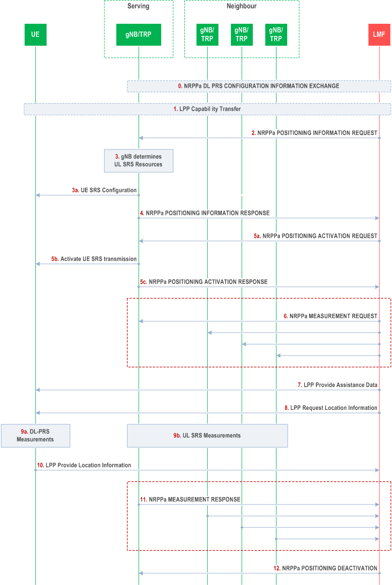
Step 0.
The LMF may use the procedure in Figure 8.10.3.2.1-1 to obtain the TRP information required for Multi-RTT positioning.
Step 1.
The LMF may request the positioning capabilities of the target device using the LPP Capability Transfer procedure described in clause 8.10.3.1.1.
Step 2.
The LMF sends a NRPPa POSITIONING INFORMATION REQUEST message to the serving gNB to request UL information for the target device as described in Figure 8.10.3.2.1-2.
Step 3.
The serving gNB determines the resources available for UL-SRS and configures the target device with the UL-SRS resource sets at step 3a.
Step 4.
The serving gNB provides the UL-SRS configuration information to the LMF in a NRPPa POSITIONING INFORMATION RESPONSE message.
Step 5a.
In the case of semi-persistent or aperiodic SRS, the LMF may request activation of UE SRS transmission by sending a NRPPa Positioning Activation Request message to the serving gNB of the target device as described in clause 8.10.3.2.3.
Step 5b.
The gNB then activates the UE SRS transmission. The target device begins the UL-SRS transmission according to the time domain behavior of UL-SRS resource configuration.
Step 5c.
The gNB sends a NRPPa Positioning Activation Response message.
Step 6.
The LMF provides the UL information to the selected gNBs in a NRPPa MEASUREMENT REQUEST message as described in clause 8.10.3.2.2. The message includes all information required to enable the gNBs/TRPs to perform the UL measurements.
Step 7.
The LMF sends a LPP Provide Assistance Data message to the target device as described in clause 8.10.3.1.2.1. The message includes any required assistance data for the target device to perform the necessary DL-PRS measurements.
Step 8.
The LMF sends a LPP Request Location Information message to request Multi-RTT measurements.
Step 9a.
The target device performs the DL-PRS measurements from all gNBs provided in the assistance data at step 7. In NTN, the target device performs the DL-PRS measurements from a single TRP at different time instances.
Step 9b.
Each gNB configured at step 6 measures the UE SRS transmissions from the target device.
Step 10.
The target device reports the DL-PRS measurements for Multi-RTT to the LMF in a LPP Provide Location Information message.
Step 11.
Each gNB reports the UE SRS measurements to the LMF in a NRPPa Measurement Response message as described in clause 8.10.3.2.2.
Step 12.
The LMF sends a NRPPa POSITIONING DEACTIVATION message to the serving gNB as described in clause 8.10.3.2.3.
Step 13.
The LMF determines the RTTs from the UE and gNB Rx-Tx time difference measurements for each gNB for which corresponding UL and DL measurements were provided at steps 10 and 11 and calculates the position of the target device.