Content for TS 38.305 Word version: 18.3.0
1…
4…
5…
6…
6.5…
6.7…
7…
7.3A…
7.4…
7.6…
7.11…
7.12…
8…
8.1.2.1a…
8.1.3…
8.2…
8.3…
8.4…
8.5…
8.6…
8.7…
8.8…
8.9…
8.10…
8.11…
8.12…
8.13…
8.14…
8.15…
A…
7.6 Procedures for On-Demand PRS transmission
7.6.1 General
7.6.2 On-Demand PRS transmission procedures
7.7 Procedures for Pre-configured Measurement Gap
7.7.1 General
7.7.2 Pre-configured Measurement Gap procedures
7.8 Procedures for Pre-configured PRS processing window
7.8.1 General
7.8.2 Pre-configured PRS processing window procedures
7.9 Positioning in RRC_INACTIVE state
7.10 Positioning in RRC_IDLE state
...
...
7.6 Procedures for On-Demand PRS transmission |R17| p. 60
7.6.1 General p. 60
On-Demand PRS transmission procedure allows the LMF to control and decide whether PRS is transmitted or not and to change the characteristics of an ongoing PRS transmission. The on-demand PRS transmission procedure can be initiated either by the UE or LMF. The actual PRS changes are requested by the LMF irrespective of whether the procedure is UE- or LMF-initiated.
7.6.2 On-Demand PRS transmission procedures p. 60
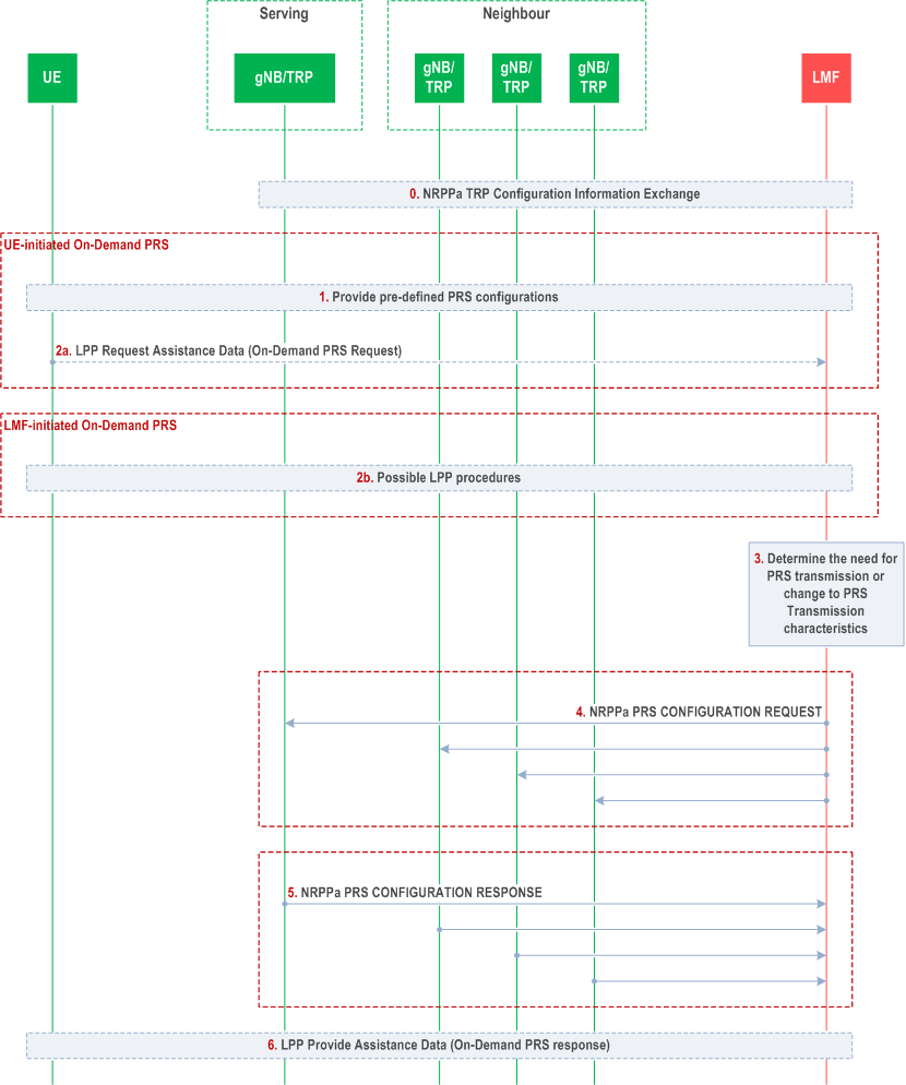
Figure 7.6.2-1 shows the general positioning procedure for On-Demand PRS transmission.
Step 0.
The LMF may receive information on the possible On-Demand PRS configurations that the gNB can support during the TRP Information Exchange procedure.
Step 1.
In case of UE-initiated On-Demand PRS, the LMF may configure the UE with pre-defined PRS configurations via LPP Provide Assistance Data message or via posSI.
Step 2a.
In case of UE-initiated On-Demand PRS, the UE sends an On-Demand PRS request to the LMF via LPP Request Assistance Data message. The On-Demand PRS request can be a request for a pre-defined PRS configuration indicated with pre-defined PRS configuration ID or explicit parameter for PRS configuration and may be a request for PRS transmission or change to the PRS transmission characteristics for positioning measurements.
Step 2b.
In case of LMF-initiated On-Demand PRS, the LMF and the UE may exchange LPP messages e.g., to obtain UE measurements or the DL-PRS positioning capabilities of the UE, etc.
Step 3.
The LMF determines the need for PRS transmission or change to the transmission characteristics of an ongoing PRS transmission.
Step 4.
The LMF requests the serving and non-serving gNBs/TRPs for new PRS transmission or PRS transmission with changes to the PRS configuration via NRPPa PRS CONFIGURATION REQUEST message.
Step 5.
The gNBs/TRPs provide the successfully configured or updated PRS transmission in the NRPPa PRS CONFIGURATION RESPONSE message accordingly.
Step 6.
LMF may provide the PRS configuration used for PRS transmission or error cause via LPP Provide Assistance Data message to the UE.
7.7 Procedures for Pre-configured Measurement Gap |R17| p. 62
7.7.1 General p. 62
The pre-configured measurement gap procedure is used by the network to provide measurement gap for NR DL-PRS measurements. The serving gNB may activate/deactivate the pre-configured measurement gap upon receiving the request from a UE or LMF.
7.7.2 Pre-configured Measurement Gap procedures p. 62
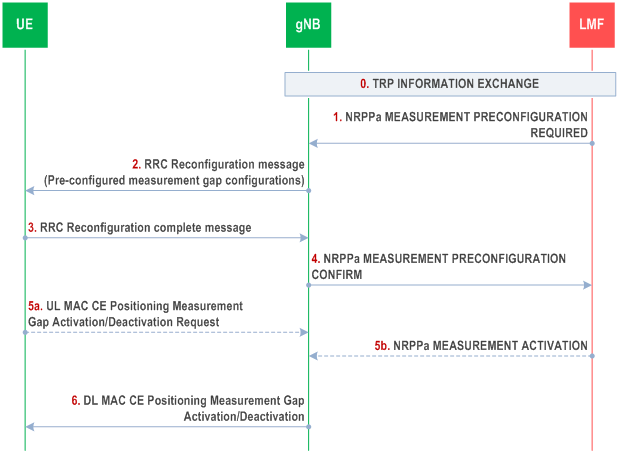
Figure 7.7.2-1 shows the procedure for the successful pre-configuration and activation of measurement gap.
Step 0.
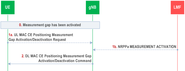
Figure 7.7.2-2 shows the procedure for the successful deactivation of measurement gap.
LMF obtains the TRP information required for positioning services from the gNBs.
Step 1.
The LMF provides the PRS information of the neighbour TRPs to the serving gNB and requests the serving gNB to configure the UE with measurement pre-configurations via NRPPa MEASUREMENT PRECONFIGURATION REQUIRED message.
Step 2.
Based on the assistance information from the LMF and the UE capability, the serving gNB decides to pre-configure the UE with measurement gap and provides pre-configured measurement gap configuration(s) with associated ID(s) to the UE by sending RRC Reconfiguration message specified in TS 38.331.
Step 3.
The UE sends RRC Reconfiguration complete message to the serving gNB to confirm the reception of pre-configured measurement gap configuration(s).
Step 4.
The serving gNB sends the confirmation message to the LMF to indicate the success of the pre-configuration via NRPPa MEASUREMENT PRECONFIGURATION CONFIRM message.
Step 5a.
If the UE requires measurement gaps for performing the requested location measurements, and the triggering condition for UL MAC CE as specified in TS 38.331 is met, the UE sends UL MAC CE Positioning Measurement Gap Activation/Deactivation Request to the serving gNB and indicates the requested measurement gap configuration based on the ID configured in step 2.
Step 5b.
LMF may send the NRPPa MEASUREMENT ACTIVATION message to request the serving gNB to activate pre-configured measurement gap.
Step 6.
Based on the request from the UE in step 5a or the request from the LMF in step 5b, the serving gNB may send DL MAC CE Positioning Measurement Gap Activation/Deactivation Command containing an ID to activate the associated measurement gap.
Step 0.
A measurement gap has been activated as shown in Figure 7.7.2-1.
Step 1a.
If the UE requires to stop performing the requested location measurements, and the triggering condition for UL MAC CE as specified in TS 38.331 is met, the UE sends UL MAC CE Positioning Measurement Gap Activation/Deactivation Request to the serving gNB to deactivate the activated measurement gap containing the ID associated with the measurement gap for positioning.
Step 1b.
LMF may send the NRPPa MEASUREMENT ACTIVATION message to request the serving gNB to deactivate pre-configured measurement gap.
Step 2.
Based on the request from the UE in step 1a or the request from the LMF in step 1b, the serving gNB may send DL MAC CE Positioning Measurement Gap Activation/Deactivation Command containing an ID to deactivate the associated measurement gap.
7.8 Procedures for Pre-configured PRS processing window |R17| p. 64
7.8.1 General p. 64
The pre-configured PRS processing window procedure is used by the network to provide PRS processing window for NR DL-PRS measurements to the UE without measurement gap. The serving gNB may activate/deactivate the pre-configured PRS processing window upon receiving the request from LMF.
7.8.2 Pre-configured PRS processing window procedures p. 64
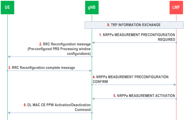
Figure 7.8.2-1 shows the procedure for the successful pre-configuration and activation of PRS processing window.
Step 0.
Figure 7.8.2-2 shows the procedure for the successful deactivation of PRS processing window.
LMF obtains the TRP information required for positioning services from the gNBs.
Step 1.
The LMF provides the PRS information of the neighbour TRPs to the serving gNB and requests the serving gNB to configure the UE with measurement pre-configurations via NRPPa MEASUREMENT PRECONFIGURATION REQUIRED message.
Step 2.
Based on the assistance information from the LMF and the UE capability, the serving gNB decides to pre-configure the UE with PRS processing window and provides pre-configured PRS processing window configuration(s) with associated ID(s) to the UE by sending RRC Reconfiguration message specified in TS 38.331.
Step 3.
The UE sends RRC Reconfiguration complete message to the serving gNB to confirm the reception of pre-configured PRS processing window configuration(s).
Step 4.
The serving gNB sends the confirmation message to the LMF to indicate the success of the pre-configuration via NRPPa MEASUREMENT PRECONFIGURATION CONFIRM message.
Step 5.
The LMF sends the NRPPa MEASUREMENT ACTIVATION message to request the serving gNB to activate the pre-configured PRS processing window.
Step 6.
Based on the request from the LMF in step 5, the serving gNB sends DL MAC CE PPW Activation/Deactivation Command containing ID(s) to activate the associated PRS processing window configuration(s).
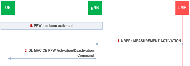
Step 0.
The PRS processing window has been activated as shown in Figure 7.8.2-1.
Step 1.
The LMF sends the NRPPa MEASUREMENT ACTIVATION message to request the serving gNB to deactivate the pre-configured PRS processing window.
Step 2.
Based on the request from the LMF in step 1, the serving gNB sends DL MAC CE PPW Activation/Deactivation Command containing ID(s) to deactivate the associated PRS processing window configuration(s).
7.9 Positioning in RRC_INACTIVE state |R17| p. 65
Positioning may be performed when a UE is in RRC_INACTIVE state. Any uplink LCS or LPP message can be transported in RRC_INACTIVE state. If the UE initiated data transmission using UL SDT, the network can send DL LCS, LPP, RRC Release message (e.g. to configure SRS for UL positioning, if it is supported) and SP Positioning SRS Activation/Deactivation MAC CE to the UE without the need of state transition.
Periodic and Semi-persistent UL-SRS transmission for positioning can be supported in RRC_INACTIVE. The UL-SRS for positioning configuration in RRC_INACTIVE state may be associated with an SRS Validity Area. The SRS Validity Area contains a list of cells in which the SRS for positioning configuration in RRC_INACTIVE state is valid. When configured with an SRS configuration for positioning along with SRS Validity Area, if the UE reselects to another cell within the SRS Validity Area during SRS transmission, the UE continues the SRS transmission, subject to validation for SRS transmission as specified in TS 38.321 and TS 38.331. When the UE reselects out of the SRS for positioning Validity Area during SRS transmission, the UE may send an "RRC Resume Request" message to the network for SRS configuration request.
The SRS for positioning configuration in RRC_INACTIVE state may be pre-configured in the target device. The target device may send an "RRC Resume Request" message to the network when a configured periodic or triggered location event has been detected to request activation of the pre-configured SRS for positioning. For preconfigured multiple SRS configurations, the UE is configured with only one SRS for positioning configuration for each validity area.
7.10 Positioning in RRC_IDLE state |R18| p. 65
Positioning measurements may be performed when a UE is in RRC_IDLE state and reported when in RRC_CONNECTED state (see also clause 6.4.2).
A UE may utilize the positioning assistance data received via broadcast (see clause 7.5) or the positioning assistance data received while in RRC_CONNECTED state when performing positioning measurements in RRC_IDLE state.