Content for TR 26.928 Word version: 18.0.0
0…
4…
4.1.2…
4.2…
4.3…
4.4…
4.5…
4.6…
4.6.7
4.7…
4.9…
5…
6…
7…
8
A…
A.4…
A.7…
A.10…
A.13
A.14
A.15
A.16
A.17
A.18…
4.6.7 Production and Capturing Systems for 3D Mesh and Point Clouds p. 40
4.6.7.1 Overview p. 40
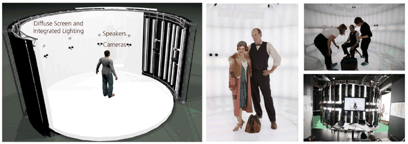
In order to capture a 3D mesh in a production facility using stereo cameras, an array of multiple cameras is placed around a recording space. A subject (for example an actor) is recorded inside the recoding space. Figure 4.6.7-1 shows an outline of one of the prototype studios as well as some example images from a production plant. In the left of Figure 4.6.7-1 a rotunda-like recording space is shown, in which multiple cameras are placed around the peripherals of the space.

Figure 4.6.7-1: Example of a capture and production facility for Point Cloud/ 3D meshes
(⇒ copy of original 3GPP image)
(⇒ copy of original 3GPP image)
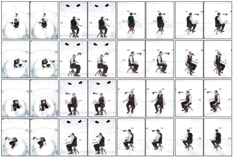
A multi-camera or multi-stereo-camera pairs setup serves as a stereo camera base unit. Each stereo camera pair records the subject(s) from a different viewpoint. For example, Figure 4.6.7-2 shows different image captures from different multi-camera setup taken at one time instance. The volumetric capture studio has an integrated illuminated background for lightning.

Figure 4.6.7-2: Example of the 32 images captured simultaneously at one time instance in a studio
(⇒ copy of original 3GPP image)
(⇒ copy of original 3GPP image)
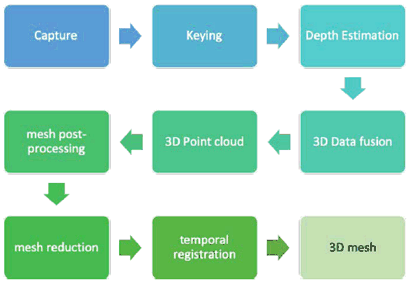
Figure 4.6.7-3 illustrates the 3D mesh production workflow. After the capture, a foreground and background segmentation process is performed in the 'keying' stage. A 'depth estimator' is applied to the captured images from each stereo pair to generate depth information with high accuracy for each pixel. From each stereo camera pair, the 3D information is stored as a colour-coded depth value in a 2D image. For example, a resulting depth map image from a stereo camera pair is shown in Figure 4.6.7-4.


Figure 4.6.7-4: Example of a dense depth map calculated per frame for each stereo camera pair
(⇒ copy of original 3GPP image)
(⇒ copy of original 3GPP image)
In the following stage, the depth information from every stereo camera pair is merged using the initial camera calibration and a related 3D fusion process. Any 3D point which is occluded by others is filtered out, resulting in an advanced foreground segmentation.
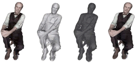
The result of the 3D fusion process is a 3D Point cloud. The 3D Point cloud is further processed by different post-processing steps such as meshing, mesh reduction and texturing, etc as shown in the Figure 4.6.7-5. The depth-based surface reconstruction results in a high-density mesh which consists of a high number of vertices and faces. In order to simplify the resulting high-density mesh to a single consistent mesh, a geometric simplification is performed. This process is called the mesh reduction. The simplified meshes are texturized using a 2D texture map in a common 2D image file format. In the final stage of the post-processing, the resulting meshes are temporally registered to obtain animated meshes.

Figure 4.6.7-5: Example of resulting point cloud (left), and 3D models such as meshing, simplification and texturing (from second left to right)
(⇒ copy of original 3GPP image)
(⇒ copy of original 3GPP image)