Content for TR 38.844 Word version: 18.0.0
6.2.2 Combined UE CBW (one cell)
6.2.2.1 General Aspects
6.2.2.2 Signalling and configuration aspects
6.2.2.3 UE architecture aspects
...
...
6.2.2 Combined UE CBW (one cell) p. 23
6.2.2.1 General Aspects p. 23
- Studied spectrum blocks covered by "main RF carrier" and "additional RF carrier"
- The "main RF carrier" is Rel-15 compatible and contains the SSB as well as all necessary broadcast information, legacy UEs and UEs which do not support this solution are able to camp on it and be connected without being aware of the "additional RF carrier"
- The "additional RF carrier" , which is partially overlapping with the "main RF carrier", is aligned to the "main RF carrier" PRB grid and utilizes further PRBs that fit in relevant spectrum block. UEs which support this solution would be reconfigured (once UE capabilities are known) in RRC_CONNECTED to use wider CBW and BWP than used for initial access.
- The "main RF carrier" and the "additional RF carrier" are treated as single cell (one carrier from baseband perspective) to allow for a single BWP to cover studied spectrum block in RRC_CONNECTED
- Both the "main RF carrier" and the "additional RF carrier" would clearly define the size and position of the guard band which allows for an unambiguous placement of the overlapping channel filters and thus prevents problems with OBUE, ACS or in-band blocking
- From UE perspective, supported in downlink only
6.2.2.2 Signalling and configuration aspects p. 24
In this section we provide further signaling details on how to support irregular channels given the 7MHz allocation as an example.
The gNB broadcasts the DL carrier bandwidth and the bandwidth of the initial BWP (BWP#0) in SIB1. For the 7MHz allocation, SIB1 would indicate DL standard channel bandwidth (i.e. 5 MHz), the initial DL BWP would be set to 5 MHz to accommodate legacy and new UEs:
Once the UE established the RRC connection, the gNB can account for the UE capabilities and re-configure the UE accordingly. At this point the gNB may override the carrier bandwidth value that the UE obtained from SIB1 and configure a dedicated BWP with a bandwidth that differs from the bandwidth of BWP#0. gNB may configure a larger bandwidth part that will cover the whole 7MHz allocation.
It should be noted that 36 PRBs do not correspond to any channel bandwidth currently defined in TS 38.101-1.
It is possible from signalling point of view to override the SIB1 channel bandwidth by the dedicated channel bandwidth signalling in RRC_CONNECTED if the UE is capable of the dedicated channel bandwidth, and if the network ensures the SIB1 channel bandwidth and dedicated channel bandwidth use the same PRB grid. New capability might be needed to support such configuration [3].
- SIB1→ servingCellConfigCommon→ downlinkConfigCommon→ frequencyInfoDL→ scs-SpecificCarrierList→ carrierBandwidth = 25 PRBs / subcarrierSpacing = 15 kHz
- SIB1→ servingCellConfigCommon→ downlinkConfigCommon→ initialDownlinkBWP→ genericParameters→ locationAndBandwidth = 25 PRBs
- ServingCellConfig→ downlinkChannelBW-PerSCS-List→ carrierBandwidth = 36 PRBs, subcarrierSpacing = 15 kHz
- ServingCellConfig→ downlinkBWP-ToAddModList→ bwp-Common→ genericParameters→ locationAndBandwidth = 36 PRBs
6.2.2.3 UE architecture aspects p. 24
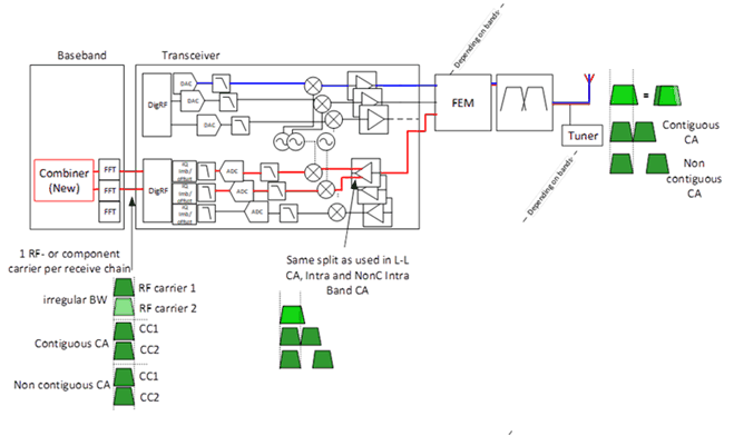
With respect to the UE architecture, the following assumptions are made (according to SID objectives):
- New (dedicated) channel filters (e.g. non-integer-multiples of 5 MHz) are not considered
- UEs not supporting this solution (both legacy and new UEs) should be able to use the next lower supported channel bandwidth in the UL and DL without implications

Figure 6.2.2.3-1: UE architecture for full BW support showing split by the use of two LOs
(⇒ copy of original 3GPP image)
(⇒ copy of original 3GPP image)
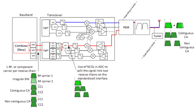
Depending on the receiver architecture and the distribution of the channel filtering between the analogue and the digital domain, it is also possible to A/D convert a frequency range that accommodates the entire irregular BW and to split the signal afterwards by means of NCOs (instead of LOs) into the 2 RF carriers with their individual channel filter positions as shown in Figure 6.2.2.3-2.

Figure 6.2.2.3-2: UE architecture for full BW support showing split by the use of NCOs
(⇒ copy of original 3GPP image)
(⇒ copy of original 3GPP image)