Content for TR 38.844 Word version: 18.0.0
6.2 Study of overlapping UE channel bandwidths
6.2.1 Overlapping UE CBWs from Network Perspective
6.2.1.1 General
6.2.1.2 Detailed description
6.2.1.3 Configuration and signalling aspects
6.2.1.4 Channel raster handling
...
...
6.2 Study of overlapping UE channel bandwidths p. 20
6.2.1 Overlapping UE CBWs from Network Perspective p. 20
6.2.1.1 General p. 20
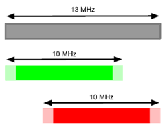
One way to utilise the whole chunk of irregular spectrum of a particular size is to combine several overlapping channels of next lower standard channel bandwidth. As an example, Figure 6.2.1.1-1 shows a case when two overlapping 10MHz carriers cover 13MHz channel bandwidth. From an individual UE perspective, each UE is configured with existing immediately lower channel bandwidth following legacy procedures and signalling: one UE can use the first 10MHz carrier, while another UE can use another carrier. In fact, both UEs can use overlapping part of the spectrum provided that the BS takes care that the overlapping region is allocated to one particular carrier at a time. It should be also noted that from the UE perspective, an existing immediately lower channel bandwidth will be always used, either for initial access (as the channel bandwidth advertised by the network) or as a dedicated channel bandwidth configured by RRC. From the network perspective, the BS will/can use the whole irregular channel bandwidth.

It is worth noting that overall capacity of the cell will be according to the irregular channel bandwidth because the BS can use the full bandwidth. However, since a particular UE will use only one carrier of a smaller bandwidth within the irregular channel bandwidth, the maximum throughput for a single UE will be less than the theoretically possible within the spectrum in case there is only a single UE in the cell. Nevertheless, since there will be multiple UEs in the cell the overall system throughput will not decrease.
6.2.1.2 Detailed description p. 21
One of the challenges associated with configuring overlapping carriers for the same frequency allocation is that both carriers should have aligned grid so that the BS can perform same FFT and schedule resources in the overlapping region.
While aligning RB grids is not an issue for bands above 3GHz that have the SCS based raster, it becomes more challenging for the sub-3GHz band that have 100kHz raster. As a result, carriers can be configured on raster points that correspond to the least common multiple of the channel raster and the RB size. As an example, the least common multiple will be 900kHz in case of the 15kHz SCS, which corresponds to 5RBs. It effectively means that overlapping carriers will not be able to address efficiently any irregular spectrum size and in some case maybe will not be applicable at all. Of course one way to improve spectrum utilisation is to allow shifting carriers in multiples of 1RB, but that will require introduction of new raster points, which will not be supported by legacy UEs.
Figure 6.2.1.2-1 presents an example for the 6MHz channel comprising two 5MHz channels. As can be seen from the figure, centre frequency distance between carriers is 900kHz, which is a multiple of 100kHz channel raster and 180kHz RB size. From an individual UE perspective, it is just a normal 5MHz carrier comprising 25RBs and having the 5MHz channel guard bands. From the BS perspective, it is a 6MHz channel with 30RBs. Figure 6.2.1.2-2 exemplifies how this approach can be used to support the 7MHz irregular channel bandwidth, in which the distance between the carriers is 1800kHz. Finally, Figure 6.2.1.2-3 shows the 11MHz channel that is supported with two 10MHz channels. Referring to Figure 6.2.1.2-1, Figure 6.2.1.2-2 and Figure 6.2.1.2-3, it should be noted that guard bands will not necessarily be symmetrical and the exact guard band size will depend on a particular spectrum allocation, its size, and how the overlapping channels are placed.

Figure 6.2.1.2-1: Detailed overview of overlapping carriers (6MHz channel with 5MHz carriers)
(⇒ copy of original 3GPP image)
(⇒ copy of original 3GPP image)

Figure 6.2.1.2-2: Detailed overview of overlapping carriers (7MHz channel with 5MHz carriers)
(⇒ copy of original 3GPP image)
(⇒ copy of original 3GPP image)

Figure 6.2.1.2-3: Detailed overview of overlapping carriers (11MHz channel with 10MHz carriers)
(⇒ copy of original 3GPP image)
(⇒ copy of original 3GPP image)
Table 6.2.1.2-1 below summarises potential number of schedulable RBs for a scenario when the next smaller overlapping channels are used. To calculate them, it is assumed that distance between individual carriers is a multiple of 900kHz and that the resulting guard bands must meet at least next smaller channel requirements. So, "Channel Nrb", and "Utilisation" represent the network view, while from the UE perspective all the parameters are the same as for the next smaller channel.
| Channel (MHz) | Next smaller channel (MHz) | Next smaller channel guard band (kHz) | Next smaller channel Nrb | Channel Nrb | Utilisation (%) |
|---|---|---|---|---|---|
| 6 | 5 | 242,5 | 25 | 30 | 90 |
| 7 | 5 | 242,5 | 25 | 35 | 90 |
| 11 | 10 | 312,5 | 52 | 57 | 93,3 |
| 12 | 10 | 312,5 | 52 | 62 | 93 |
| 13 | 10 | 312,5 | 52 | 67 | 92,8 |
Table 6.2.1.2-2 presents similar calculations for the number of available RBs with overlapping carriers, but for the 30kHz SCS. As can be seen from the Table, a solution based on the 30kHz SCS overlapping carriers does not provide a good spectral utilisation for certain non-standard channel bandwidths due to the reason that the "distance" between carriers raster points must be a multiple of 1800kHz. Because of that, channel bandwidths such as 7 and 12MHz have more or less good utilisation, whereas 6 and 11MHz do not provide any benefit at all.
| Channel (MHz) | Next smaller channel (MHz) | Next smaller channel guard band (kHz) | Next smaller channel Nrb | Channel Nrb | Utilisation (%) |
|---|---|---|---|---|---|
| 6 | 5 | 505 | 11 | 11 | 66 |
| 7 | 5 | 505 | 11 | 16 | 82,3 |
| 11 | 10 | 665 | 24 | 24 | 78,5 |
| 12 | 10 | 665 | 24 | 29 | 87 |
| 13 | 10 | 665 | 24 | 29 | 80,3 |
To suppport two overlapping carriers, the network can consider using one or two SSBs. To be more precise, since the the SSB bandwidth is 3.6MHz and the CORESET#0 bandwidth is 4.32MHz, a single SSB/CORESET#0 can be placed into a common part between two overlapping channels. However, this approach works only if the overlapping part is at least 4.32MHz, e.g. it is not applicable to irregular channels smaller than 10MHz. So, some irregular channel bandwidth will need two SSB/CORESET#0. In this case, at least for irregular channel bandwidths smaller than 10MHz the network broadcasts two separate SSBs, one for each overlapping regular carrier. If a particular irregular channel bandwidth does not allow for placing two SSBs in the same time slots, then the network will have to ensure that they are "multiplexed" accordingly in the time domain.
From the RAN2 specifications perspective, a single cell has a single cell-defining SSB, the channel bandwidth configuration broadcast in SIB1, CORESET#0, and the initial BWP. Thus, a single "common" SSB for two overlapping channels will effectively define only one of the overlapping channels as perceived by the UE (refer to sub-clause 6.2.1.3 for more information on configuration and signalling aspects with one and two SSBs).
| Channel (MHz) | Number of SSB/CORESET#0 | Time multiplexing for 2 SSBs is needed |
|---|---|---|
| 6 | 2 | yes |
| 7 | 2 | yes |
| 11 | 1 or 2 | no |
| 12 | 1 or 2 | no |
| 13 | 1 or 2 | no |
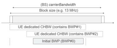
Figure 6.2.1.2-4 shows an example for the 13MHz irregular channel with a single/common SSB configured in the overlapping part of two 10MHz carriers.

Figure 6.2.1.2-4: Using overlapping carriers with single overlapping SSB (example for 13MHz)
(⇒ copy of original 3GPP image)
(⇒ copy of original 3GPP image)
6.2.1.3 Configuration and signalling aspects p. 23
Since from an individual UE perspective each overlapping carrier is just a legacy channel bandwidth, the existing signalling applies. As an example, for the 7MHz allocation the UE can be configured with the 5MHz channel bandwidth, and the initial bandwidth part can be also 5MHz.
If the network configures two SSBs for an overlapping channel, then from the UE perspective each overlapping channel is perceived as an independent cell and a UE can camp on each cell following the existing cell (re-)selection procedures. If the network configures one "common" SSB, then from the UE perspective only one of the overlapping channels is perceived as a cell and some UEs will be re-configured with a dedicated channel bandwidth to another overlapping channel.
- SIB1→ servingCellConfigCommon→ downlinkConfigCommon→ frequencyInfoDL→ scs-SpecificCarrierList→ carrierBandwidth = 25 PRBs / subcarrierSpacing = 15 kHz
- SIB1→ servingCellConfigCommon→ downlinkConfigCommon→ initialDownlinkBWP→ genericParameters→ locationAndBandwidth = 25 PRBs
6.2.1.4 Channel raster handling p. 23
The UE channel BWs have to be backwards compatible such that this scheme works for existing UEs, hence, they would have to be deployed on the 100kHz raster used in the low FR1 bands. As such, the UE channels have to be deployed at a distance which is a multiple of 900kHz (common denominator between the RB size of 180kHz and 100kHz channel raster granularity).
The base station channel encompasses the overlapping UE channels. In the case that the distance between the UE channel centers is an even multiple of 900kHz, the center of the base station channel will also fall on a 100kHz multiple. In the case of an odd 900kHz multiple, the center of the base station transmission bandwidth configuration would fall in the middle of the 900kHz interval between the overlapping UE channel centers. This might require some additional specification work for BS.