Content for TR 38.844 Word version: 18.0.0
6.1.3 UE channel filters p. 18
A typical UE architecture utilises a number of filters of two major types - analogue and digital - and it is generally up to the UE implementation how they are combined. Nevertheless, it is often the case that a UE uses first the wideband analogue filter which typically covers a whole band. In addition to that, a UE may use another NR channel bandwidth specific analogue filter, premise function on which is to filter our non-adjacent blockers. However, since even the NR channel bandwidth specific analogue filter cannot ensure "brick-wall" like filtering, a UE also applies digital filter after ADC to eliminate adjacent interferer. Depending on the UE implementation, the digital filter is a combination of the hardware and software components that allow the UE to apply the corresponding filter coefficients to support a wide range of standard channels, e.g. from 5MHz to 100MHz in case of FR1.
As an example, consider Figure 6.1.3-1. In this example, RBs are scheduled close to the NR band edge. The potential adjacent interferer below the band edge will be removed by the CBW filter with no degradation of ACS at the lower side of the irregular BW since the filters have the same capability as the regular CBW operation.

Figure 6.1.3-1: Example of the NW utilizing the lower RBs near the NR band edge with BWP
(⇒ copy of original 3GPP image)
(⇒ copy of original 3GPP image)
However, for the scenario in the Figure 6.1.3-2 the wider channel filter cannot protect against adjacent interferer(s) when the irregular spectrum block is narrower than the channel filter and/or there are adjacent interferers on both sides.
Current specifications do not define how a UE configures its digital filter within the configured channel bandwidth. So, in the provided example below, a UE implementation may configure the digital filter in accordance with the carrier bandwidth "ignoring" the actual smaller bandwidth part size. This is illustrated further in Figure 6.1.3-2. The wanted signal is smaller than 10MHz, but the UE filter is always set to 10MHz as signalled by the network. As can be seen, if there is an adjacent interferer, then it can "leak" into the wanted signal region.

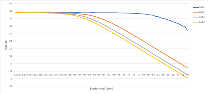
To estimate anticipated performance described in Figure 6.1.3-2 when a UE configures its digital filter according to the channel bandwidth potentially allowing the adjacent interferer to "leak" into the wanted signal area, a series of measurements were conducted using the same testbed and setup as used for the commercial device conformance testing. The adjacent interfering signal is always set in such a way that it is right next to the wanted irregular channel bandwidth signal. Table 6.1.3-1 below summarises adjacent interfering channel parameters used in measurements, where adjacent interferer offset is the offset from the wanted signal center to the adjacent interfering signal center.
| Irregular channel (MHz) | Effective bandwidth (MHz) | Adjacent interferer offset (MHz) | Adjacent interferer bandwidth (MHz) |
|---|---|---|---|
| 9 | 8.28 | 7 | 5 |
| 8 | 7.2 | 6.5 | |
| 7 | 6.3 | 6 | |
| 6 | 5.22 | 5.5 |
The following common parameters were applied:
- Center frequency: 1850MHz
- UE channel: 10MHz
- Wanted signal level at UE antenna: -82dBm
- Adjacent interferer level at UE antenna: from -120dBm to -50dBm in step of 1dB
- Adjacent interferer: 5MHz, 16QAM, SCS 15kHz (3GPP standard ACS test)

Figure 6.1.3-3: Estimated SNR depending on the adjacent interferer level
(⇒ copy of original 3GPP image)
(⇒ copy of original 3GPP image)
To further reduce the risk of ACS reduction, as shown in this second example in Figure 6.1.3-2 and Figure 6.1.3-3, it is possible for new UEs to align their digital filter to the actual smaller bandwidth part within the wider analogue CBW filter bandwidth.