Content for TS 37.340 Word version: 18.2.0
1…
4…
4.2…
4.3…
5…
7…
8…
9
10…
10.2…
10.2.2…
10.3…
10.3.2
10.4…
10.5…
10.5.2
10.6
10.7…
10.8…
10.9…
10.10…
10.11…
10.12…
10.12.2
10.13…
10.14…
10.15
10.16…
10.17…
10.18…
10.19…
10.20
11…
A
B…
10.8 Master Node to eNB/gNB Change p. 79
10.8.1 EN-DC p. 79
The Master Node to eNB Change procedure is used to transfer context data from a source MN/SN to a target eNB.

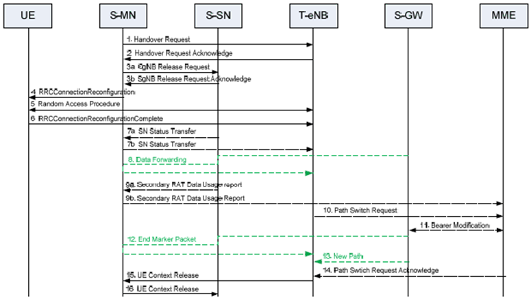
Figure 10.8.1-1 shows an example signalling flow for the Master Node to eNB Change procedure:
Step 1.
The source MN starts the MN to eNB Change procedure by initiating the X2 Handover Preparation procedure, including both MCG and SCG configuration.
Step 2.
The target eNB includes the field in HO command which releases SCG configuration, and may also provide forwarding addresses to the source MN.
Step 3.
If the allocation of target eNB resources was successful, the MN initiates the release of the source SN resources towards the source SN including a Cause indicating MCG mobility. The SN acknowledges the release request. If data forwarding is needed, the MN provides data forwarding addresses to the source SN. Reception of the SgNB Release Request message triggers the source SN to stop providing user data to the UE and, if applicable, to start data forwarding.
Step 4.
The MN triggers the UE to apply the new configuration. Upon receiving the new configuration, the UE releases the entire SCG configuration.
Step 5/6.
The UE synchronizes to the target eNB.
Step 7.
For SN terminated bearers using RLC AM, the SN sends the SN Status Transfer message, which the source MN sends then to the target eNB.
Step 8.
If applicable, data forwarding takes place from the source side.
Step 9a.
The source SN sends the Secondary RAT Data Usagee Report message to the source MN and includes the data volumes delivered to and received from the UE over the NR radio for the related E-RABs.
Step 9b.
The source MN sends the Secondary RAT Report message to MME to provide information on the used NR resource.
Step 10-14.
The target eNB initiates the S1 Path Switch procedure.
Step 15.
The target eNB initiates the UE Context Release procedure towards the source MN.
Step 16.
Upon reception of the UE Context Release message, the SN releases radio and C-plane related resources associated to the UE context. Any ongoing data forwarding may continue.
10.8.2 MR-DC with 5GC p. 81
The MN to ng-eNB/gNB Change procedure is used to transfer UE context data from a source MN/SN to a target ng-eNB/gNB. Both the cases where the source MN and the target node belong to the same RAT (i.e. they are both ng-eNBs or both gNBs) and the cases where the source MN and the target node belong to different RATs are supported.

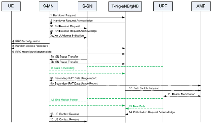
Figure 10.8.2-1 shows an example signalling flow for the MN to ng-eNB/gNB Change procedure:
Step 1.
The source MN starts the MN to ng-eNB/gNB Change procedure by initiating the Xn Handover Preparation procedure, including both MCG and SCG configuration.
Step 2.
The target ng-eNB/gNB includes the field in HO command which releases the SCG configuration, and may also provide forwarding addresses to the source MN.
Step 3.
If the resource allocation of target ng-eNB/gNB was successful, the MN initiates the release of the source SN resources towards the source SN including a Cause indicating MCG mobility. The SN acknowledges the release request. If data forwarding is needed, the MN provides data forwarding addresses to the source SN. Reception of the SN Release Request message triggers the source SN to stop providing user data to the UE and, if applicable, to start data forwarding.
Step 4.
The MN triggers the UE to perform HO and apply the new configuration. Upon receiving the new configuration, the UE releases the entire SCG configuration.
Step 5/6.
The UE synchronizes to the target ng-eNB/gNB.
Step 7.
If PDCP termination point is changed for bearers using RLC AM, the SN sends the SN Status Transfer message, which the source MN sends then to the target ng-eNB/gNB.
Step 8.
If applicable, data forwarding takes place from the source side.
Step 9a.
The source SN sends the Secondary RAT Data Usage Report message to the source MN and includes the data volumes delivered to and received from the UE as described in clause 10.11.2.
Step 9b.
The source MN sends the Secondary RAT Report message to AMF to provide information on the used NR/E-UTRA resource.
Step 10-14.
The target ng-eNB/gNB initiates the Path Switch procedure.
Step 15.
The target ng-eNB/gNB initiates the UE Context Release procedure towards the source MN.
Step 16.
Upon reception of the UE Context Release message from the MN, the source SN releases radio and C-plane related resources associated to the UE context. Any ongoing data forwarding may continue.