Content for TS 37.340 Word version: 18.2.0
1…
4…
4.2…
4.3…
5…
7…
8…
9
10…
10.2…
10.2.2…
10.3…
10.3.2
10.4…
10.5…
10.5.2
10.6
10.7…
10.8…
10.9…
10.10…
10.11…
10.12…
10.12.2
10.13…
10.14…
10.15
10.16…
10.17…
10.18…
10.19…
10.20
11…
A
B…
4.2 Radio Protocol Architecture p. 11
4.2.1 Control Plane p. 11
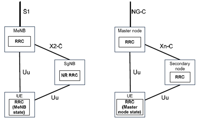
In MR-DC, the UE has a single RRC state, based on the MN RRC and a single C-plane connection towards the Core Network. Figure 4.2.1-1 illustrates the Control plane architecture for MR-DC. Each radio node has its own RRC entity (E-UTRA version if the node is an eNB or NR version if the node is a gNB) which can generate RRC PDUs to be sent to the UE.
RRC PDUs generated by the SN can be transported via the MN to the UE. The MN always sends the initial SN RRC configuration via MCG SRB (SRB1), but subsequent reconfigurations may be transported via MN or SN. When transporting RRC PDU from the SN, the MN does not modify the UE configuration provided by the SN.
In E-UTRA connected to EPC, at initial connection establishment SRB1 uses E-UTRA PDCP. If the UE supports EN-DC, regardless whether EN-DC is configured or not, after initial connection establishment, MCG SRBs (SRB1 and SRB2) can be configured by the network to use either E-UTRA PDCP or NR PDCP (either SRB1 and SRB2 are both configured with E-UTRA PDCP, or they are both configured with NR PDCP). Change from E-UTRA PDCP to NR PDCP (or vice-versa) is supported via a handover procedure (reconfiguration with mobility) or, for the initial change of SRB1 from E-UTRA PDCP to NR PDCP, with a reconfiguration without mobility before the initial security activation.
If the SN is a gNB (i.e. for EN-DC, NGEN-DC and NR-DC), the UE can be configured to establish a SRB with the SN (SRB3) to enable RRC PDUs for the SN to be sent directly between the UE and the SN. RRC PDUs for the SN can only be transported directly to the UE for SN RRC reconfiguration not requiring any coordination with the MN. Measurement reporting for mobility within the SN can be done directly from the UE to the SN if SRB3 is configured.
In NR-DC, the UE can be configured to establish a SRB with the SN (SRB5) to enable RRC messages which include application layer measurement report information to be sent directly between the UE and the SN. The application measurement report can be sent directly from the UE to the SN if SRB5 is configured and indicated by the network for the application measurement reporting.
Split SRB is supported for all MR-DC options, allowing duplication of RRC PDUs generated by the MN, via the direct path and via the SN. Split SRB uses NR PDCP. This version of the specification does not support the duplication of RRC PDUs generated by the SN via the MN and SN paths.
In EN-DC, the SCG configuration is kept in the UE during suspension. During connection resumption, if the UE supports resuming with EN-DC, the UE can be configured to release, restore, or reconfigure the SCG configuration. Otherwise, the UE releases the SCG configuration (but not the radio bearer configuration) during resumption initiation.
In MR-DC with 5GC, the UE stores the PDCP/SDAP configuration and the SCG configuration when moving to RRC Inactive. During connection resumption, if the UE supports resuming with MR-DC, the UE can be configured to release, restore, or reconfigure the SCG configuration. Otherwise, it releases the SCG configuration.
4.2.2 User Plane p. 12
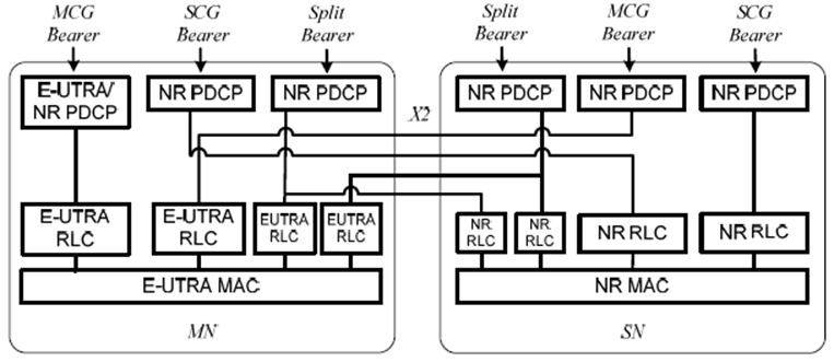
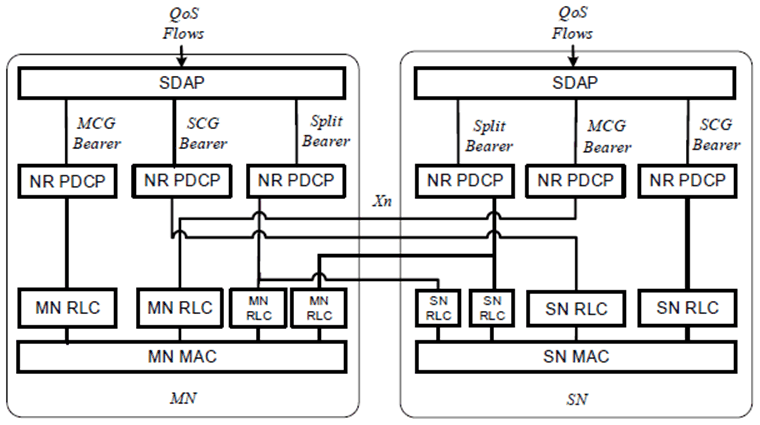
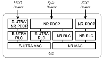
In MR-DC, from a UE perspective, three bearer types exist: MCG bearer, SCG bearer and split bearer. These three bearer types are depicted in Figure 4.2.2-1 for MR-DC with EPC (EN-DC) and in Figure 4.2.2-2 for MR-DC with 5GC (NGEN-DC, NE-DC and NR-DC).
In E-UTRA connected to EPC, if the UE supports EN-DC, regardless whether EN-DC is configured or not, the network can configure either E-UTRA PDCP or NR PDCP for MN terminated MCG bearers while NR PDCP is always used for all other bearers. Change from E-UTRA to NR PDCP or vice-versa can be performed via a reconfiguration procedure (with or without handover), either using release and add of the DRBs or using the full configuration option.
In MR-DC with 5GC, NR PDCP is always used for all bearer types. In NGEN-DC, E-UTRA RLC/MAC is used in the MN while NR RLC/MAC is used in the SN. In NE-DC, NR RLC/MAC is used in the MN while E-UTRA RLC/MAC is used in the SN. In NR-DC, NR RLC/MAC is used in both MN and SN.
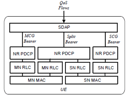
From a network perspective, each bearer (MCG, SCG and split bearer) can be terminated either in MN or in SN. Network side protocol termination options are shown in Figure 4.2.2-3 for MR-DC with EPC (EN-DC) and in Figure 4.2.2-4 for MR-DC with 5GC (NGEN-DC, NE-DC and NR-DC).
