Content for TS 37.340 Word version: 18.2.0
1…
4…
4.2…
4.3…
5…
7…
8…
9
10…
10.2…
10.2.2…
10.3…
10.3.2
10.4…
10.5…
10.5.2
10.6
10.7…
10.8…
10.9…
10.10…
10.11…
10.12…
10.12.2
10.13…
10.14…
10.15
10.16…
10.17…
10.18…
10.19…
10.20
11…
A
B…
4.3 Network interfaces
4.3.1 Control Plane
4.3.1.1 Common MR-DC principles
4.3.1.2 MR-DC with EPC
4.3.1.3 MR-DC with 5GC
4.3.2 User Plane
4.3.2.1 Common MR-DC principles
4.3.2.2 MR-DC with EPC
4.3.2.3 MR-DC with 5GC
...
...
4.3 Network interfaces p. 14
4.3.1 Control Plane p. 14
4.3.1.1 Common MR-DC principles p. 14
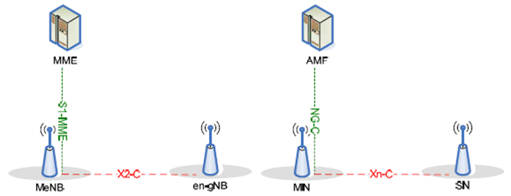
In MR-DC, there is an interface between the MN and the SN for control plane signalling and coordination. For each MR-DC UE, there is also one control plane connection between the MN and a corresponding CN entity. The MN and the SN involved in MR-DC for a certain UE control their radio resources and are primarily responsible for allocating radio resources of their cells.
Figure 4.3.1.1-1 shows C-plane connectivity of MN and SN involved in MR-DC for a certain UE.

4.3.1.2 MR-DC with EPC p. 15
In MR-DC with EPC (EN-DC), the involved core network entity is the MME. S1-MME is terminated in MN and the MN and the SN are interconnected via X2-C.
4.3.1.3 MR-DC with 5GC p. 15
In MR-DC with 5GC (NGEN-DC, NE-DC and NR-DC), the involved core network entity is the AMF. NG-C is terminated in the MN and the MN and the SN are interconnected via Xn-C.
4.3.2 User Plane p. 15
4.3.2.1 Common MR-DC principles p. 15
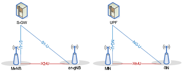
There are different U-plane connectivity options of the MN and SN involved in MR-DC for a certain UE, as shown in Figure 4.3.2.1-1. The U-plane connectivity depends on the bearer option configured:
- For MN terminated bearers, the user plane connection to the CN entity is terminated in the MN;
- For SN terminated bearers, the user plane connection to the CN entity is terminated in the SN;
-
The transport of user plane data over the Uu either involves MCG or SCG radio resources or both:
- For MCG bearers, only MCG radio resources are involved;
- For SCG bearers, only SCG radio resources are involved;
- For split bearers, both MCG and SCG radio resources are involved.
- For split bearers, MN terminated SCG bearers and SN terminated MCG bearers, PDCP data is transferred between the MN and the SN via the MN-SN user plane interface.

4.3.2.2 MR-DC with EPC p. 16
For MR-DC with EPC (EN-DC), X2-U interface is the user plane interface between MN and SN, and S1-U is the user plane interface between the MN, the SN or both and the S-GW.
4.3.2.3 MR-DC with 5GC p. 16
For MR-DC with 5GC (NGEN-DC, NE-DC and inter-gNB NR-DC), Xn-U interface is the user plane interface between MN and SN, and NG-U is the user plane interface between the MN, the SN or both and the UPF.