Content for TS 37.340 Word version: 18.2.0
1…
4…
4.2…
4.3…
5…
7…
8…
9
10…
10.2…
10.2.2…
10.3…
10.3.2
10.4…
10.5…
10.5.2
10.6
10.7…
10.8…
10.9…
10.10…
10.11…
10.12…
10.12.2
10.13…
10.14…
10.15
10.16…
10.17…
10.18…
10.19…
10.20
11…
A
B…
10.3 Secondary Node Modification (MN/SN initiated) p. 39
10.3.1 EN-DC p. 39
The Secondary Node Modification procedure may be initiated either by the MN or by the SN and be used to modify, establish or release bearer contexts, to transfer bearer contexts to and from the SN or to modify other properties of the UE context within the same SN. It may also be used to transfer an NR RRC message from the SN to the UE via the MN and the response from the UE via MN to the SN (e.g. when SRB3 is not used). In case of CPA or inter-SN CPC, this procedure is used to modify CPA or inter-SN CPC configuration within the same candidate SN. In case of CPA or inter-SN CPC, this procedure may also be triggered by the candidate SN to add some prepared PSCells from the suggested list or cancel part of the prepared PSCells. In case of intra-SN CPC, this procedure is used to configure, modify or release intra-SN CPC configuration. This procedure may be initiated by the MN or SN to request the SN or MN to deactivate or activate the SCG.
The Secondary Node modification procedure does not necessarily need to involve signalling towards the UE.
MN initiated SN Modification
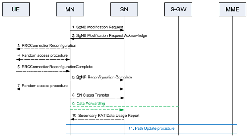
The MN uses the procedure to initiate configuration changes of the SCG within the same SN, e.g. the addition, modification or release of SCG bearer(s) and the SCG RLC bearer of split bearer(s), as well as configuration changes for SN terminated MCG bearers. Bearer termination point change is realized by adding the new bearer configuration and releasing the old bearer configuration within a single MN initiated SN Modification procedure for the respective E-RAB. The MN uses this procedure to perform handover within the same MN while keeping the SN. The MN also uses the procedure to query the current SCG configuration, e.g. when delta configuration is applied in an MN initiated SN change. The MN also uses the procedure to provide the S-RLF related information to the SN. The MN also uses this procedure to activate or deactivate the SCG. The MN may not use the procedure to initiate the addition, modification or release of SCG SCells. The SN may reject the request, except if it concerns the release of SN terminated bearer(s) or the SCG RLC bearer of MN terminated bearer(s), or if it is used to perform handover within the same MN while keeping the SN. Figure 10.3.1-1 shows an example signalling flow for an MN initiated SN Modification procedure.
Step 1.
SN initiated SN Modification with MN involvement
The MN sends the SgNB Modification Request message, which may contain bearer context related or other UE context related information, data forwarding address information (if applicable) and the requested SCG configuration information, including the UE capability coordination result to be used as basis for the reconfiguration by the SN. The MN may request the SCG to be activated or deactivated. In case a security key update in the SN is required, a new SgNB Security Key is included. In case of SCG RLC re-establishment for E-RABs configured with an MN terminated bearer with an SCG RLC bearer for which no bearer type change is performed, the MN provides a new UL GTP tunnel endpoint to the SN. The SN shall continue sending UL PDCP PDUs to the MN with the previous UL GTP tunnel endpoint until it re-establishes the RLC and use the new UL GTP tunnel endpoint after re-establishment. In case of PDCP re-establishment for E-RABs configured with an SN terminated bearer with an MCG RLC bearer for which no bearer type change is performed, the MN provides a new DL GTP tunnel endpoint to the SN. The SN shall continue sending DL PDCP PDUs to the MN with the previous DL GTP tunnel endpoint until it performs PDCP re-establishment and use the new DL GTP tunnel endpoint starting with the PDCP re-establishment.
Step 2.
The SN responds with the SgNB Modification Request Acknowledge message, which may contain SCG radio resource configuration information within a NR RRC configuration message and data forwarding address information (if applicable). If the MN requested the SCG to be activated or deactivated, the SN indicates whether the SCG is activated or deactivated. In case of a security key update (with or without PSCell change), for E-RABs configured with the MN terminated bearer option that require X2-U resources between the MN and the SN, for which no bearer type change is performed, the SN provides a new DL GTP tunnel endpoint to the MN. The MN shall continue sending DL PDCP PDUs to the SN with the previous DL GTP tunnel endpoint until it performs PDCP re-establishment or PDCP data recovery, and use the new DL GTP tunnel endpoint starting with the PDCP re-establishment or data recovery. In case of a security key update (with or without PSCell change), for E-RABs configured with the SN terminated bearer option that require X2-U resources between the MN and the SN, for which no bearer type change is performed, the SN provides a new UL GTP tunnel endpoint to the MN. The MN shall continue sending UL PDCP PDUs to the SN with the previous UL GTP tunnel endpoint until it re-establishes the RLC and use the new UL GTP tunnel endpoint after re-establishment.
Step 3-5.
The MN initiates the RRC connection reconfiguration procedure, including the NR RRC configuration message. The UE applies the new configuration, synchronizes to the MN (if instructed, in case of intra-MN handover) and replies with RRCConnectionReconfigurationComplete, including a NR RRC response message, if needed. In case the UE is unable to comply with (part of) the configuration included in the RRCConnectionReconfiguration message, it performs the reconfiguration failure procedure.
Step 6.
Upon successful completion of the reconfiguration, the success of the procedure is indicated in the SgNB Reconfiguration Complete message.
Step 7.
If instructed, the UE performs synchronisation towards the PSCell of the SN as described in SgNB addition procedure. Otherwise, the UE may perform UL transmission after having applied the new configuration.
Step 8.
If PDCP termination point is changed for bearers using RLC AM, and when RRC full configuration is not used, the SN Status Transfer takes place between the MN and the SN (Figure 10.3.1-1 depicts the case where a bearer context is transferred from the MN to the SN).
Step 9.
If applicable, data forwarding between MN and the SN takes place (Figure 10.3.1-1 depicts the case where a bearer context is transferred from the MN to the SN).
Step 10.
The SN sends the Secondary RAT Data Usage Report message to the MN and includes the data volumes delivered to and received from the UE over the NR radio for the E-RABs to be released and for the E-RABs for which the S1 UL GTP Tunnel endpoint was requested to be modified.
Step 11.
If applicable, a path update is performed.
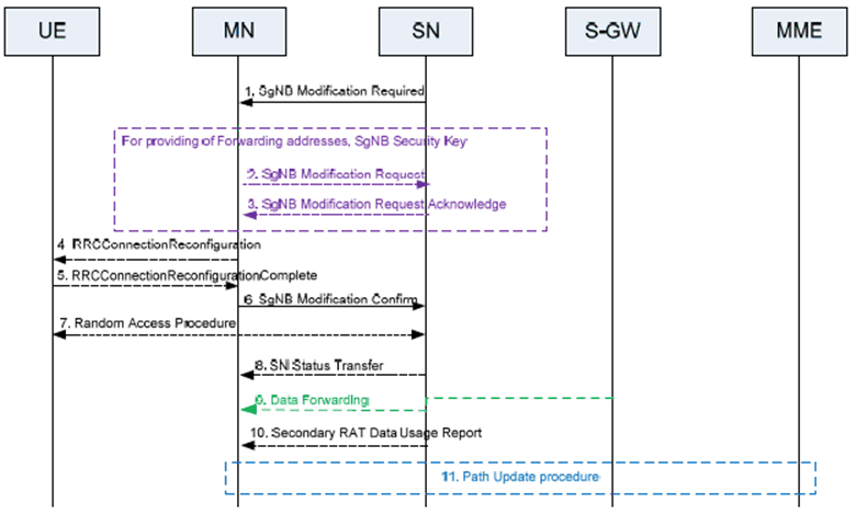
The SN uses the procedure to perform configuration changes of the SCG within the same SN, e.g. to trigger the release of SCG bearer(s) and the SCG RLC bearer of split bearer(s) (upon which the MN may release the bearer or maintain current bearer type or reconfigure it to an MCG bearer, either MN terminated or SN terminated), to trigger the release of SCG resources (e.g., release SCG lower layer resources but keep SN), and to trigger PSCell change (e.g. when a new security key is required or when the MN needs to perform PDCP data recovery). The MN cannot reject the release request of SCG bearer and the SCG RLC bearer of a split bearer and the release request of SCG resources. The SN also uses this procedure to activate or deactivate the SCG. The MN shall either accept modification of all of the requested SCG bearer(s) and the SCG RLC bearer of split bearer(s) and the request of activation or deactivation of the SCG, or fail the procedure. Figure 10.3.1-2 shows an example signalling flow for an SN initiated SgNB Modification procedure, with MN involvement.
Step 1.
SN initiated SN Modification without MN involvement
The SN sends the SgNB Modification Required message including a NR RRC configuration message, which may contain bearer context related, other UE context related information and the new SCG radio resource configuration. The SN may request the SCG to be activated or deactivated. For bearer release or modification, a corresponding E-RAB list is included in the SgNB Modification Required message. In case of change of security key, the PDCP Change Indication indicates that a S-KgNB update is required. In case the MN needs to perform PDCP data recovery, the PDCP Change Indication indicates that PDCP data recovery is required. In case SN decides to trigger SCG release, the E-RABs to be modified list includes all the E-RABs of the UE with SCG resource indicated as not present for each E-RAB.
The SN can decide whether the change of security key is required.
Step 2/3.
The MN initiated SN Modification procedure may be triggered by the SN Modification Required message (e.g. to provide information such as data forwarding addresses, new SN security key, measurement gap, etc...)
Step 4.
The MN sends the RRCConnectionReconfiguration message including a NR RRC configuration message to the UE including the new SCG radio resource configuration.
Step 5.
The UE applies the new configuration and sends the RRCConnectionReconfigurationComplete message, including an encoded NR RRC response message, if needed. In case the UE is unable to comply with (part of) the configuration included in the RRCConnectionReconfiguration message, it performs the reconfiguration failure procedure.
Step 6.
Upon successful completion of the reconfiguration, the success of the procedure is indicated in the SgNB Modification Confirm message containing the encoded NR RRC response message, if received from the UE.
Step 7.
If instructed, the UE performs synchronisation towards the PSCell of the SN as described in SN addition procedure. Otherwise, the UE may perform UL transmission after having applied the new configuration.
Step 8.
If PDCP termination point is changed for bearers using RLC AM, and when RRC full configuration is not used, the SN Status Transfer takes place between the MN and the SN (Figure 10.3.1-2 depicts the case where a bearer context is transferred from the SN to the MN).
Step 9.
If applicable, data forwarding between MN and the SN takes place (Figure 10.3.1-2 depicts the case where a bearer context is transferred from the SN to the MN).
Step 10.
The SN sends the Secondary RAT Data Usage Report message to the MN and includes the data volumes delivered to and received from the UE over the NR radio for the E-RABs to be released.
Step 11.
If applicable, a path update is performed.
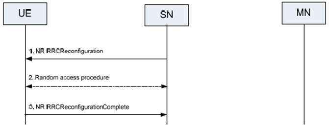
The SN initiated modification without MN involved procedure is used to modify the configuration within SN in case no coordination with MN is required, including the addition/modification/release of SCG SCell and PSCell change (e.g. when the security key does not need to be changed and the MN does not need to be involved in PDCP recovery). The SN may initiate the procedure to configure, modify or release intra-SN CPC configuration within the same SN. Figure 10.3.1-3 shows an example signalling flow for SN initiated SN modification procedure, without MN involvement. The SN can decide whether the Random Access procedure is required.
Step 1.
SN initiated Conditional SN Modification without MN involvement (SRB3 is used)
The SN sends the RRCReconfiguration message to the UE through SRB3. The UE applies the new configuration. In case the UE is unable to comply with (part of) the configuration included in the RRCReconfiguration message, it performs the reconfiguration failure procedure.
Step 2.
If instructed, the UE performs synchronisation towards the PSCell of the SN.
Step 3.
The UE replies with the RRCReconfigurationComplete message.
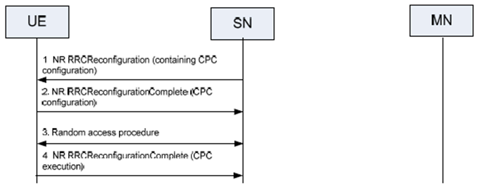
The SN initiates the procedure when it needs to transfer an NR RRC message to the UE and SRB3 is used to configure CPC.
Step 1.
Transfer of an NR RRC message to/from the UE (when SRB3 is not used)
The SN sends the RRCReconfiguration message including CPC configuration to the UE through SRB3.
Step 2.
The UE applies the new configuration. In case the UE is unable to comply with (part of) the configuration included in the RRCReconfiguration message, it performs the reconfiguration failure procedure. The UE starts evaluating the CPC execution conditions for the candidate PSCell(s). The UE maintains connection with the source PSCell and replies with the RRCReconfigurationComplete message to the SN via SRB3.
Step 3.
If at least one CPC candidate PSCell satisfies the corresponding CPC execution condition, the UE detaches from the source PSCell, applies the stored configuration corresponding to the selected candidate PSCell and synchronises to the candidate PSCell.
Step 4.
The UE completes the CPC execution procedure by sending an RRCReconfigurationComplete message to the new PSCell.

The SN initiates the procedure when it needs to transfer an NR RRC message to the UE and SRB3 is not used.
Step 1.
SN initiated Conditional SN Modification without MN involvement (SRB3 is not used)
The SN initiates the procedure by sending the SgNB Modification Required to the MN.
Step 2.
The MN forwards the NR RRC message to the UE in the RRCConnectionReconfiguration message.
Step 3.
The UE applies the new configuration and replies with the RRCConnectionReconfigurationComplete message. In case the UE is unable to comply with (part of) the configuration included in the NR RRC message, it performs the reconfiguration failure procedure.
Step 4.
The MN forwards the NR RRC response message, if received from the UE, to the SN in the SgNB Modification Confirm message.
Step 5.
If instructed, the UE performs synchronisation towards the PSCell of the SN as described in SgNB Addition procedure. Otherwise the UE may perform UL transmission after having applied the new configuration.
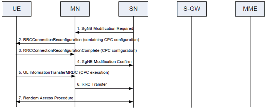
The SN initiates the procedure when it needs to transfer an NR RRC message to the UE and SRB3 is not used to configure intra-SN CPC.
Step 1.
The SN initiates the procedure by sending the SgNB Modification Required to the MN including the SN RRC reconfiguration message with CPC configuration.
Step 2.
The MN forwards the SN RRC reconfiguration message to the UE including it in the RRCConnectionReconfiguration message.
Step 3.
The UE replies with the RRCConnectionReconfigurationComplete message by including the SN RRC reconfiguration complete message. In case the UE is unable to comply with (part of) the configuration included in the SN RRC reconfiguration message, it performs the reconfiguration failure procedure. The UE maintains connection with source PSCell after receiving CPC configuration, and starts evaluating the CPC execution conditions for the candidate PSCell(s).
Step 4.
The MN forwards the SN RRC response message, if received from the UE, to the SN by including it in the SgNB Modification Confirm message.
Step 5.
If at least one CPC candidate PSCell satisfies the corresponding CPC execution condition, the UE completes the CPC execution procedure by an ULInformationTransferMRDC message to the MN which includes an embedded RRCReconfigurationComplete message to the selected target PSCell.
Step 6.
The RRCReconfigurationComplete message is forwarded to the SN embedded in RRC Transfer message.
Step 7.
The UE detaches from the source PSCell, applies the stored corresponding configuration and synchronises to the selected candidate PSCell.