Content for TS 33.127 Word version: 19.1.0
0…
5…
5.4…
5.6…
5.7…
6…
6.2.2…
6.2.3…
6.2.5…
6.3…
6.3.3…
6.3.4…
6.4…
7…
7.3…
7.4…
7.4.7…
7.5…
7.6…
7.7…
7.8…
7.9…
7.10…
7.11…
7.12…
7.13…
7.14…
7.15…
7.16…
8…
A…
A.2…
A.3…
A.4…
B…
D…
E…
A.3 Multiple DN connections in a PDU session
A.3.1 General
A.3.2 Topology view for a non-roaming scenario
...
...
A.3 Multiple DN connections in a PDU session p. 165
A.3.1 General p. 165
According to TS 23.501, a PDU session can involve multiple UPFs, but regardless of how many UPFs are involved in the session, the session only connects to a single DN through one or more DN connections (i.e. connections to the same DN).
When a PDU session involves multiple UPFs, the interception of user plane packets can be done in two ways:
- At one UPF (branching UPF) through which all the user plane packets pass through.
- At anchor UPFs.
A.3.2 Topology view for a non-roaming scenario p. 165
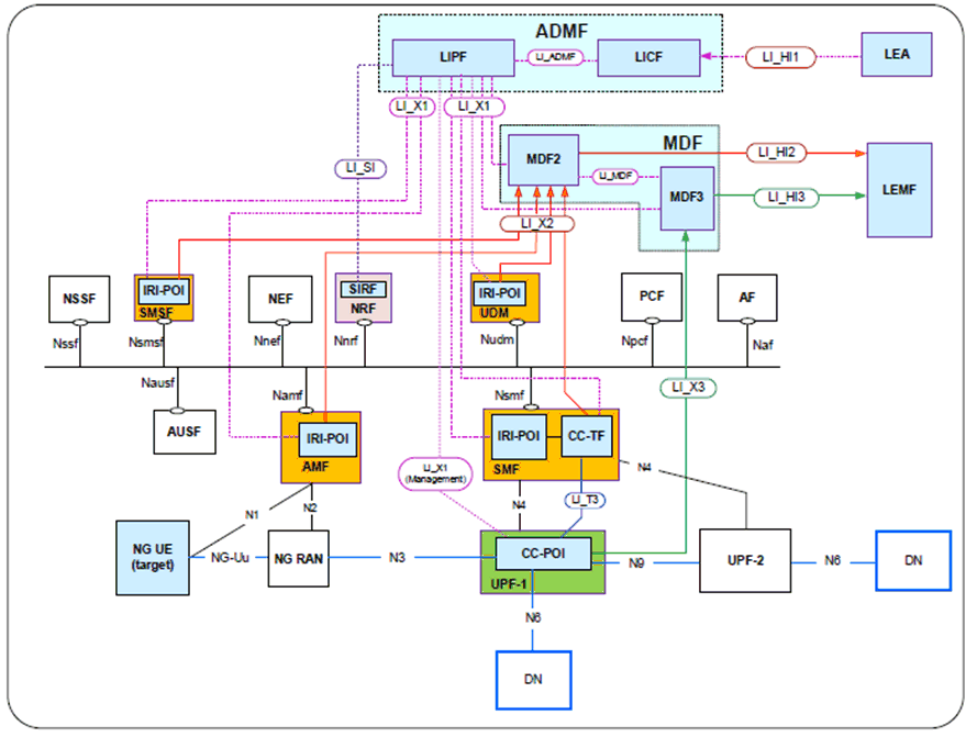
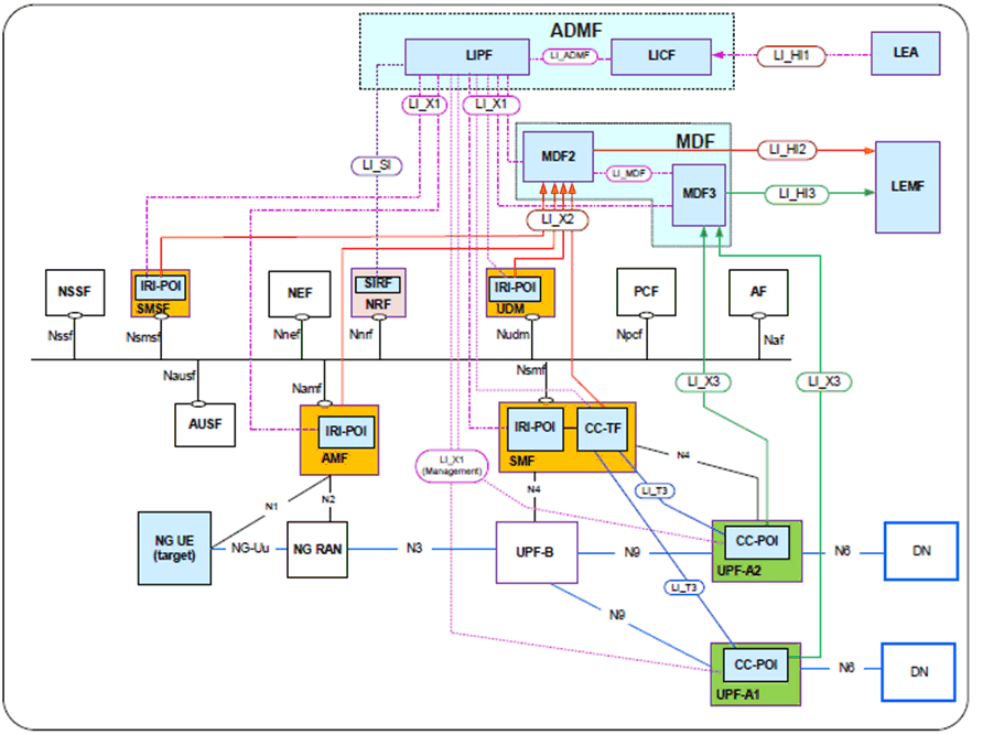
The overall network configurations to illustrate the LI with multiple DN connections (to the same DN) in a PDU session is illustrated in Figure A.3.2-1 and Figure A.3.2-2.
The 5G core system is shown using the service-based representation (as shown in TS 23.501) with the use of point-to-point LI system.

The IRI-POIs present in the AMF, MME, UDM, SMSF and SMF deliver the xIRI to the MDF2 and CC-POI present in the branching UPF (shown as UPF-1) on the common path to both DN connections delivers the xCC to the MDF3. The MDF3 address to CC-POI present in UPF-1 is provided by the CC-TF present in the SMF over LI_T3 reference point. In this view, all user plane packets pass through UPF-1.
The LIPF present in the ADMF provisions the IRI-POIs and the CC-TF present in the NFs with the intercept related data. The LI_X1 interfaces between the LIPF and the UPF is to monitor the user plane data.

The IRI-POIs present in the AMF, MME, UDM, SMSF and SMF deliver the xIRI to the MDF2. In this example, there is a branching UPF (UPF-B), an anchor UPF for the DN (UPF-A1) and another anchor UPF for the same DN (UPF-A2). The second approach (i.e. CC interception at the anchor UPFs) mentioned in clause A.3.1 is used to provide the CC interception. The UPF-A1 delivers the xCC generated from the user plane packets that flow from UE to the DN via UPF-A1 to the MDF3. The CC-POI present in the UPF-A2 delivers the xCC generated from the user plane packets that flow UE to the DN via UPF-A2 to the MDF3. The MDF3 address in the CC-POIs present in UPF-1 and UPF-2 are provided by the CC-TF present in the SMF over LI_T3 reference point.
The LIPF present in the ADMF provisions the IRI-POIs and the CC-TF present in the NFs with the intercept related data. The LI_X1 interfaces between the LIPF and the UPFs are to monitor the user plane data.