Content for ETSI TS 102 221 PDF version: 18.2.0
0…
4…
5…
6…
7…
7.2.3…
7.3…
7.3.2…
7.4…
8…
9…
10…
10.2…
11…
11.1.2…
11.1.9…
11.1.14…
11.1.19…
11.1.20…
11.1.21…
11.2…
11.3…
12…
13…
14…
15
A
B
C…
D
E…
F…
G…
H…
I
J…
K…
L…
M…
N…
O…
4 Physical characteristics
4.0a Introduction
4.0 UICC Form Factors
4.0.0 Generic requirements
4.0.1 ID-1 UICC
4.0.2 Plug-in UICC
4.0.3 Mini-UICC
4.0.4 4FF
4.1 ID-1 UICC
4.2 Plug-in UICC
4.3 Mini-UICC
4.4 Environmental conditions for card operation and storage
4.5 Contacts
4.5.1 Provision of contacts
4.5.1.1 Terminal
4.5.1.2 UICC
4.5.2 Contact activation and deactivationm
4.5.2.1 Contacts assigned by the present document
4.5.2.2 Optional contacts
4.5.3 Inactive contacts
4.5.4 Contact pressure
...
...
4 Physical characteristics p. 21
4.0a Introduction p. 21
The provisions of clause 4 apply to the LSE base.
4.0 UICC Form Factors p. 21
4.0.0 Generic requirements p. 21
The UICC shall be either a removable hardware module (removable UICC) or a non-removable separate hardware module embedded (e.g. soldered) in the terminal.
A removable UICC shall be one of the form factors (format) specified by the present document, i.e. ID-1 UICC, plug-in UICC, mini-UICC or 4FF.
A terminal that uses a UICC in a removable hardware module, shall support at least one of the above mentioned form factors.
The physical characteristics of all types of UICCs shall be in accordance with ISO/IEC 7816-1 [9] and ISO/IEC 7816-2 [10] unless otherwise specified by the present document. The following additional requirements shall be applied to ensure correct operation in a Telecom environment.
4.0.1 ID-1 UICC p. 22
The physical characteristics of the ID-1 UICC shall conform to ISO/IEC 7816-1 [9] and ISO/IEC 7816-2 [10].
The terminal shall accept embossed ID-1 UICCs. The embossing shall be in accordance with ISO/IEC 7811-1 [8]. The contacts of the ID-1 UICC shall be located on the front (embossed face, see ISO/IEC 7810 [7]) of the card.
4.0.2 Plug-in UICC p. 22
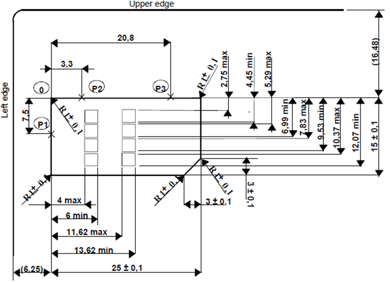
The Plug-in UICC shall have a width of 25 mm, a height of 15 mm, a thickness the same as an ID-1 UICC and a feature for orientation.
Annex A of ISO/IEC 7816-2 [10] applies with the location of the reference points adapted to the smaller size. The three reference points P1, P2 and P3 measure 7,5 mm, 3,3 mm and 20,8 mm, respectively, from 0. The values in Figure 2 of ISO/IEC 7816-2 [10] are replaced by the corresponding values of Figure 4.1.
The physical characteristics of the Plug-in UICC (Plug-in card) are defined in the present document.

4.0.3 Mini-UICC p. 23
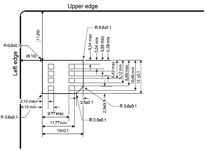
The Mini-UICC shall have a width of 15 mm, a height of 12 mm, a thickness the same as an ID-1 UICC and a feature for orientation.
Annex A of ISO/IEC 7816-2 [10] applies with the location of the reference points adapted to the smaller size below Figure 4.2. The values in Figure 2 of ISO/IEC 7816-2 [10] are replaced by the corresponding values of Figure 4.2.
The physical characteristics of the Mini-UICC are defined in the present document.

4.0.4 4FF p. 23
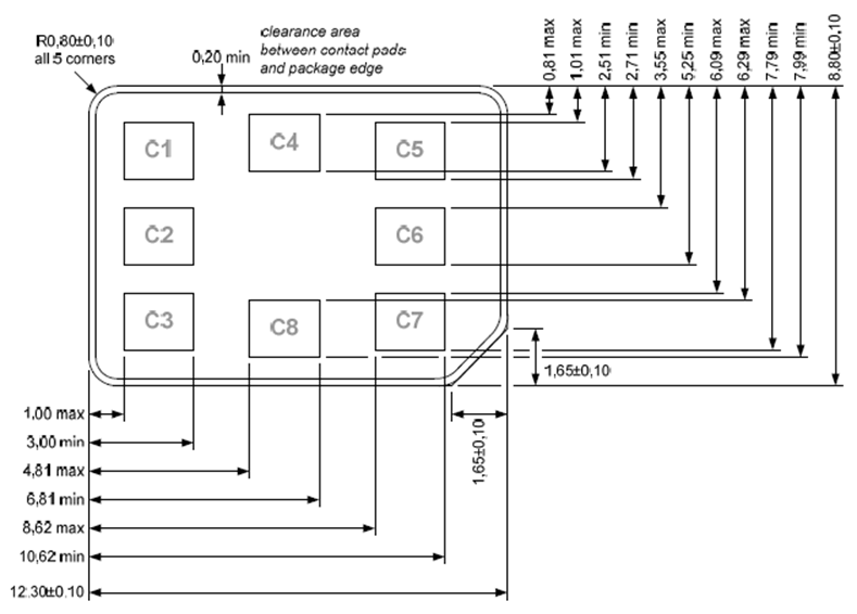
The 4FF shall have a width of 12,3 mm ± 0,1 mm and a height of 8,8 mm ± 0,1 mm, with a thickness range of 0,67 mm + 0,03 mm/-0,07 mm.
Annex A of ISO/IEC 7816-2 [10] applies with the location of the reference points adapted to the smaller size defined below in Figure 4.3. The values in Figure 2 of the ISO/IEC 7816-2 [10] are replaced by the corresponding values of Figure 4.3.
Optionally, the 4FF may be supplied within a card whose width and length are compliant with the ID-1 UICC dimensions but thickness compliant with 4FF. In that case, the 4FF shall be located from 18,22 mm from the top edge of the card and 9,25 mm from the left edge of the card.
The physical characteristics of 4FF are defined in the present document.
The 4FF shall comply with all the characteristics in ISO/IEC 7816-1 [9], except for bending and torsion properties, which apply only to the ID1 form factor. The definition of bending and torsion properties for the 4FF is FFS.

4.1 ID-1 UICC p. 24
The contents of this clause have been moved to clause 4.0.1.
4.2 Plug-in UICC p. 24
The contents of this clause have been moved to clause 4.0.2.
4.3 Mini-UICC p. 24
The contents of this clause have been moved to clause 4.0.3.
4.4 Environmental conditions for card operation and storage p. 24
4.4.0 Standard UICC environmental conditions p. 24
The standard temperature range for storage and full operational use shall be between -25 °C and +85 °C.
4.4.1 Specific UICC environmental conditions p. 25
4.4.1.0 Specific UICC environmental conditions indication p. 25
The support of specific UICC environmental conditions is optional for the UICC.
It is up to an application specification to specify the required specific environmental conditions to be supported by the UICC. If an application specification does not specify particular specific UICC environmental conditions then the UICC supports the standard environmental conditions for card operation and storage, as specified in the present document.
If the UICC supports specific environmental conditions, the indication mechanism, as specified in the present document, shall be supported.
4.4.1.1 Temperature range for specific UICC environmental conditions p. 25
The support of an extended temperature range is optional for the UICC.
The temperature ranges for full operational use and storage for specific UICC environmental conditions are defined in Table 4.1.
| Temperature class | Range |
|---|---|
| A | -40 °C to +85 °C ambient temperature range |
| B | -40 °C to +105 °C ambient temperature range |
| C | -40 °C to +125 °C ambient temperature range |
4.4.1.2 High humidity p. 25
The support of the extended humidity condition is optional for the UICC.
A UICC supporting high humidity shall withstand the test conditions as described within JEDEC ESD22-A101D.01 [23] with 1 000 hour duration.
4.5 Contacts p. 25
4.5.1 Provision of contacts p. 25
4.5.1.1 Terminal p. 25
Contacting elements in the terminal in positions C4 and C8 are optional. If present and not used, they shall either be pulled to state L or present a high impedance to the UICC. If it is determined that the UICC is a multi-application UICC, or if the terminal supports optional interfaces using these contacts, then these contacts may be used.
Contact C6 need not be provided for Plug-in/Mini-UICC/4FF cards or any card if the terminal does not support class A operating conditions (see ISO/IEC 7816-3 [11]). Contact C6 shall be provided if the terminal supports the optional interface defined in ETSI TS 102 613 [19].
If present and not used by an optional interface, C6 shall present a high impedance to the UICC or be connected to Gnd.
4.5.1.2 UICC p. 25
Contacts C4 and C8 need not be provided by the UICC. If provided, they shall not be connected internally in the UICC if the UICC only contains a Telecom application and is not using these contacts for an additional interface. For 4FF, these contacts may alternatively be connected to Gnd if the UICC is not using them for an additional interface.
Contact C6 shall not be bonded in the UICC for any function other than supplying Vpp or when the UICC supports the optional interface defined in ETSI TS 102 613 [19].
4.5.2 Contact activation and deactivationm p. 26
4.5.2.1 Contacts assigned by the present document p. 26
When using the interface defined in the present document, the terminal shall connect, activate and deactivate the UICC through the contacts C1, C2, C3, C5, C7, in accordance with the operating procedures specified in ISO/IEC 7816-3 [11].
The terminal may switch on and off the clock on contact CLK while the RST contact remains in state L.
For any voltage level, monitored during the activation sequence, or during the deactivation sequence following normal power-down, the order of the contact activation/deactivation shall be respected.
It is recommended that whenever possible, the deactivation sequence defined in ISO/IEC 7816-3 [11] should be followed by the terminal on all occasions when the terminal is powered down.
If the UICC clock is already stopped and is not restarted, the terminal may deactivate all the contacts in any order, provided that all signals reach low level before Vcc leaves high level. If the UICC clock is already stopped and is restarted before the deactivation sequence, then the deactivation sequence specified in ISO/IEC 7816-3 [11] shall be followed.
When Vpp is connected to Vcc, as allowed in the present document for terminals supporting class A operation conditions only, then Vpp shall be activated and deactivated with Vcc, at the time of the Vcc activation/deactivation, as specified in the sequences of ISO/IEC 7816-3 [11].
4.5.2.2 Optional contacts p. 26
The use of contacts C4 and C8 for the Inter-Chip USB interface is specified in ETSI TS 102 600 [18].
The use of contact C6 for the UICC-CLF interface is specified in ETSI TS 102 613 [19].
4.5.3 Inactive contacts p. 26
The voltages on contacts C1, C2, C3, C6 and C7 of the terminal shall be in the range 0 V ± 0,4 V referenced to ground (C5) when the terminal is switched off with the power source connected to the terminal and when the optional interface defined in ETSI TS 102 613 [19] is not used. The measurement equipment shall have a resistance of 50 kΩ when measuring the voltage on C2, C3, C6 and C7. The resistance shall be 10 kΩ when measuring the voltage on C1.
4.5.4 Contact pressure p. 26
The contact pressure shall be large enough to ensure reliable and continuous contact (e.g. to overcome oxidization and to prevent interruption caused by vibration). The radius of any curvature of the contacting elements shall be greater than or equal to 0,8 mm over the contact area.
Under no circumstances shall the contact force exceed 0,5 N per contact.
Care shall be taken to avoid undue point pressure to the area of the UICC opposite to the contact area. Such pressure is potentially damaging to the components within the UICC.