Content for TS 23.548 Word version: 19.1.0
1…
4…
4.3
5…
6…
6.2.2.3…
6.2.3…
6.2.3.2.3…
6.2.3.2.5…
6.2.3.3…
6.3…
6.4…
6.5…
6.6
6.7…
6.7.2.4…
6.7.2.6…
6.7.3…
6.8…
6.10…
7…
A
B…
F…
F EAS Relocation on Simultaneous Connectivity over Source and Target PSA p. 89
This Annex describes how EAS relocation can make use of network capabilities that, at PSA change, provide simultaneous connectivity over the source and the target PSA during a transient period.
At PSA change, simultaneous connectivity to Application over former and new PSA allows the application to build its own EAS relocation solution and minimize the impact on latency:
- If the decision for when to start using a target EAS is taken by the application, this decision can consider application specific aspects, like for example, the time interval between packets or end of a video frame to minimize impact on latency.
- When there are multiple applications on a PDU Session, if connectivity over the former PSA is maintained for some time, each application can schedule EAS relocation to suit the application specific needs without interfering with the other applications.

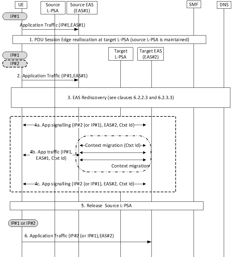
The user has established a PDU Session. This PDU Session has a local PSA (source L-PSA), which could be the PSA of a PDU Session with Distributed Anchor connectivity or one additional local PSA of a PDU Session with Session Breakout. There has been an EAS Discovery procedure as described in clauses 6.2.2.2 and 6.2.3.2 (the procedure is conditioned to the connectivity model) for one or more applications. Application traffic is served by source EAS over the Local PSA.
Step 1.
User mobility triggers SMF to select a new Local PSA (target L-PSA) that is closer to current user location. In this scenario, the re-anchoring procedures that provide Simultaneous Connectivity over Source and Target PSA are described in TS 23.502:
Step 2.
- For Distributed Anchor, in clause 4.3.5.2 for Change of SSC mode 3 PDU Session Anchor with multiple PDU Sessions and in clause 4.3.5.3 for Change of SSC mode 3 PDU Session Anchor with IPv6 Multi-homed PDU Session.
- For Session Breakout, in clause 4.3.5.7 for Simultaneous change of Branching Point or UL CL and additional PSA for a PDU Session.
When the connectivity is available on target L-PSA, the connectivity via source L-PSA is still available during certain time (that is provisioned and controlled as described in these TS 23.502 procedures). The application traffic can continue to run over the established UE-EAS connections.
Step 3.
The EAS Rediscovery Procedures described in clauses 6.2.2.3 and 6.2.3.3 allow the UE to discover a new EAS (i.e. target EAS) for the application that is closer to the UE over the new path (there could be multiple triggers as described in those respective clauses). If multiple applications are being served by this PDU Session, each of them performs rediscovery. This discovery procedure may lead to EAS reselection.
Step 4.
New L4 connections may now be established between the UE and the target EAS with the following considerations:
Step 5.
- For Distributed anchor or session breakout with MH, the UE uses the IP address /prefix associated with the target PSA (that is referred to as IP#2 in Figure F-1).
- For Session breakout with ULCL, there has not been connection/IP address change. Same IP address is still used by UE (that is referred to as IP#1 in Figure F-1).
- In case that SMF notifies an AF for the early and/or late notification in Step 1, based on the notifications, the AF can interact with the source Application server, which can recreate the context to the target EAS and then provide switching instructions to the Application client.
- The Application server can recreate the service context when first contacted by the client using a Context Id: when suitable, the application client sets up a connection to the target EAS including a Context Id. The target EAS uses this Context Id to retrieve the latest service context available and subsequent updates, if needed.
- The Application server can recreate the context when first contacted by the client using a Context Id: the application client sets up a connection to the target EAS but for some time it sends traffic to both source and target EAS. In this way it triggers the context migration before the actual EAS switch.
- The source Application server is able to provide the client with switching instructions when a new EAS is selected: upon UE request (if UE selected) or as an EAS initiative (if server selected), the source EAS provides the Application client with switching instructions while it continues to serve traffic and drives any context migration towards the selected target EAS.
At some points all traffic for all applications in this session are sending traffic to their target EAS only and traffic ceases over the source L-PSA. The source L-PSA is then released. The timers should be set to allow EAS relocation.
Step 6.
UE only maintains connection(s) to target EAS(s).