Content for TS 23.292 Word version: 18.0.0
1…
4…
5…
7…
7.2…
7.3…
7.3.2.2…
7.3.2.2.4…
7.4…
7.4.2.2…
7.4.2.2.3…
7.4.2.2.7…
7.5…
7.6…
7.6.1.2.2.6…
7.6.1.2.3…
7.6.1.2.3.5…
7.6.1.2.3.6…
7.6.2…
7.6.2.7
7.6.2.8…
7.6.2.11…
7.6.3…
7.7…
7.7.2…
7.9…
7.9.2…
7.9.2.4
7.9.2.5
8…
A…
G…
H…
H.5…
H.5.3…
H Service Domain Centralization in IMS (SeDoC)
H.1 High level description and principles
H.2 Architecture model and reference points
H.2.1 Reference architecture
H.2.2 Functional Entities
H.2.3 Reference points
H.4 Procedures and flows for non roaming users
H.4.1 Authentication/Registration for own users not roaming
H.4.2 Originating session for own users not roaming
H.4.3 Terminating session for own users not roaming
H.4.4 SMS-MO for own users not roaming
...
...
H Service Domain Centralization in IMS (SeDoC) |R14| p. 128
H.1 High level description and principles p. 128
This Annex describes an optional architecture configuration that centralizes all services, including emergency calls and SMS, within the IMS domain for all users roaming in that network independent of access used, i.e. it replaces service execution of the CS service domain with service logic execution in IMS only. The service profile for all users is soley provided by the IMS domain. For inbound roamers not supporting IMS or ICS in HPLMN therefore a temporary IMS subscription is created and service is handled locally in the VPLMN.
The architecture configuration utilizes the "Registration and Authentication procedure utilizing IMS Authorization", which enables the option to remove subscriber related data from the VLR and use data of the IMS domain instead, e.g. the HSS. An interworking function provides the support for inbound and outbound roaming in networks not supporting IMS or ICS.
This architecture configuration has no impact to UEs, no impact to interconnection interfaces of the roaming partner, no impact access networks (e.g. CS access) and does not require changes of specifications (e.g. TS 24.008).
The basic principles of this solution are that CS access is mapped to IMS and PS access uses "native" IMS (VoLTE) but there is a single service domain for both accesses in IMS. The user profile is solely provided by IMS domain. For the migration phase the SeDoC enabled network operator is required to provide legacy support for inbound roamers. Long term target is that the service for inbound roamer be provided by the HPLMN, i.e. the VPLMN IMS-GWs (IBCFs) would relay towards home IMS service infrastructure.
H.2 Architecture model and reference points p. 128
H.2.1 Reference architecture p. 128
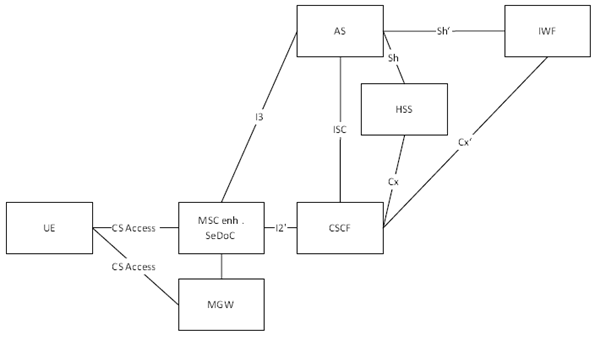
The basic principles described in previous clause require the introduction of a CS access to IMS gateway function, i.e. the MSC Server enhanced for SeDoC and an interworking function (ICS IWF) to the reference architecture. The MSC Server enhanced for SeDoC maps GSM access procedures to IMS procedures but does not store user profile data, i.e. the VLR functionality is extracted and is placed for own users into the HSS and for inbound roamer into an ICS-IWF. By doing this the internal IMS architecture does not need to introduce new interfaces.

H.2.2 Functional Entities p. 129
H.2.2.1 MSC Server enhanced for SeDoC p. 129
The MSC Server enhanced for SeDoC terminates CS Access and maps it to respective IMS procedures.
At high level the MSC Server enhanced for SeDoC performs the following functionality on the control plane:
-
towards the UE:
- terminates the A (GERAN) and Iu-cs interfaces (UTRAN) when the UE accesses via a CS RAT.
-
towards the IP Multimedia Subsystem:
- Terminates the I2' interface to the x-CSCF.
- Terminates I3 to the Telephony Application Server.
-
towards legacy networks:
- terminates the G and E interface towards MSC Servers.
- terminates ISUP signalling towards PSTN.
H.2.2.1.1 Main differences to MSC Server enhanced for ICS p. 129
The MSC Server enhanced for SeDoC is based on the MSC Server enhanced for ICS, associated MGW as defined in clause 5.3.3 of this specification, TS 23.216 and TS 23.237 with the following amendments.
H.2.2.1.2 Call control solely done in IMS p. 129
Call Control (CC) functionality is essentially required only for the A/Iu-cs side of the MSC Server enhanced for SeDoC. Some local call control i.e.to treat "non UE detected emergency call" (Germany: 110) as emergency call and. route to E-CSCF is required. Remaining Call Control functionality is done by IMS in the same way as for PS calls. Therefore the MSC Server enhanced for SeDoC behaves as P-CSCF/ATCF from viewpoint of I/S/E-CSCF, SCC-AS and MSC.
Radio Resource Management (RR) and Mobility Management (MM) remain unchanged.
H.2.2.1.3 No VLR functionality p. 130
MSC Server enhanced for SeDoC does not include VLR functionality, i.e. there is also no D-Interface to the HLR. User Service Profile data and user service profile (i.e. identity, supplementary services) are handled in the IMS domain only. MSC Server enhanced for SeDoC just need to store user data related to radio access and RR/MM/CC procedures (e.g. IMSI, IMEI, TMSI, etc.).
H.2.2.1.4 Mapping of CS procedures to IMS procedures p. 130
The MSC Server enhanced for SeDoC terminates CS Access and maps it to respective IMS procedures.
H.2.2.1.5 Call Control procedures p. 130
Call Control procedures from the mobile CS user interface (A, Iu) are mapped towards IMS interface, i.e. I2 (SIP) towards IMS core in order to support the mapping of:
- MOC & MTC based on A/Iu to respective IMS procedures
- SMS-MO & SMS-MT based on A/Iu to respective IMS/IP-SM procedures
H.2.2.1.6 Supplementary Services Management procedures p. 130
Supplementary Services Management procedures from the mobile CS user interface (A, Iu) are mapped towards IMS interfaces, i.e. I3-IF (Ut, XCAP) towards IMS MMTEL AS.
H.2.2.1.7 Mapping of IMS procedures to CS procedures p. 130
IMS specific procedures that need to be mapped to appropriate GSM procedures are:
- early media (uni/bi-directional through-connect of media path).
-
multiple early dialogues (due to forking on remote side (e.g. MSIM scenario):
- i.e. MSC Server enhanced for SeDoC serving the originating user needs to map multiple early SIP dialogues to one GSM dialogue towards the GSM device.
H.2.2.1.8 Procedures which can be handled without IMS interaction p. 130
Various MSC-Server procedures which can be handled without IMS interaction remain within the MSC Server enhanced for SeDoC. This includes e.g. handover to/from other MSC Server enhanced for SeDoC or VMSC (original MSC Server enhanced for SeDoC remains anchor after handover).
H.2.2.1.9 SMS support considerations p. 130
In order to properly support SMS a SIP based replacement for MAP based SMS alerting procedures (reachability check) is needed, i.e. to set "not reachable" flag in case of unsuccessful SMS-MT and re-register if user is reachable again.
Upon unsuccessful SMS-MT delivery (no response from terminal) the MSC Server enhanced for SeDoC needs to activate a "Not Reachable" (NR) flag (similar to GSM MSC). In case of "NR flag = TRUE" and receipt of any message from the terminal, the MSC Server enhanced for SeDoC needs to re-register towards IMS-Core.
In case of unsuccessful SMS-MT to an attached user, the IP-SM-GW shall not initiate supervision in packet core network (Sh request to HSS).
After unsuccessful SMS-MT delivery, the IP-SM-GW sets a "Not Reachable" flag. Due to this flag a re-registration (and other messages received from the terminal) will trigger the standard retry mechanisms.
H.2.2.1.10 Location p. 131
MSC Server enhanced for SeDoC provides with PANI header the network provided location information according to cell-id received from radio access network (RAN). This information may be used by applications to differentiate between 2/3G Access via MSC Server enhanced for SeDoC and 4G Access via P-CSCF.
H.2.2.1.11 CS Data support p. 131
CS Data is used analogously to a voice call: A data terminal equipment (modem) establishes a connection to another terminal (modem). The connection setup is controlled by the IMS Core, the data stream can be transported transparently with already available codecs (e.g., "clear mode"/G7.11).
H.2.2.2 ICS Interworking Function p. 131
The ICS interworking function is introduced in order to support inbound and outbound roamers in networks that do not support IMS or ICS. Detailed in clause H.5.2.2.
H.2.3 Reference points p. 131
H.2.3.1 Reference Point MSC Server enhanced for SeDoC - CSCF (I2' Reference Point) p. 131
The I2' reference point is based on I2 functionality as defined in TS 23.216, TS 23.237 and in clause 5.4.2.
Additionally it supports the "Registration and Authentication procedure utilizing IMS Authorization" as specified in Annex G.
H.2.3.2 Reference Point MSC Server enhanced for SeDoC - TAS (I3 Reference Point) p. 131
The I3 is used between the MSC Server enhanced for SeDoC and the TAS to interwork CS signalling and communication service setting procedures, as defined in clause 4.5 of this specification.
H.2.3.3 Reference Point ICS-IWF - CSCF (Cx' Reference Point) p. 131
The Cx' reference point is based on Cx functionality similar to the procedures of S-CSCF - HSS communication. It supports information transfer between CSCF and ICS-IWF.
The main procedures that require information transfer between CSCF and ICS-IWF are:
- Procedures related to Serving CSCF assignment
- Procedures related to routing information retrieval from ICS-IWF to CSCF
- Procedures related to authorisation (e.g. checking of roaming agreement)
- Procedures related to authentication: transfer of security parameters of the subscriber between ICS-IWF and CSCF
- Procedures related to filter control: transfer of filter parameters of the subscriber from ICS-IWF to CSCF
H.2.3.4 Reference Point ICS-IWF - AS (Sh' Reference Point) p. 132
The Sh' reference point is based on Sh functionality similar to the procedures of AS - HSS communication. It supports information transfer between AS and HSS.
H.4 Procedures and flows for non roaming users p. 132
H.4.1 Authentication/Registration for own users not roaming p. 132
For authentication/registration procedure for own users not roaming please refer to Annex G of this specification.
H.4.2 Originating session for own users not roaming p. 132
Session origination for own users is specified in clause 7.3.2.1.2 Origination using I2 reference point
H.4.3 Terminating session for own users not roaming p. 132
Session termination for own users is specified in clause 7.4.2.1.2 Termination using I2 reference point
H.4.4 SMS-MO for own users not roaming p. 132

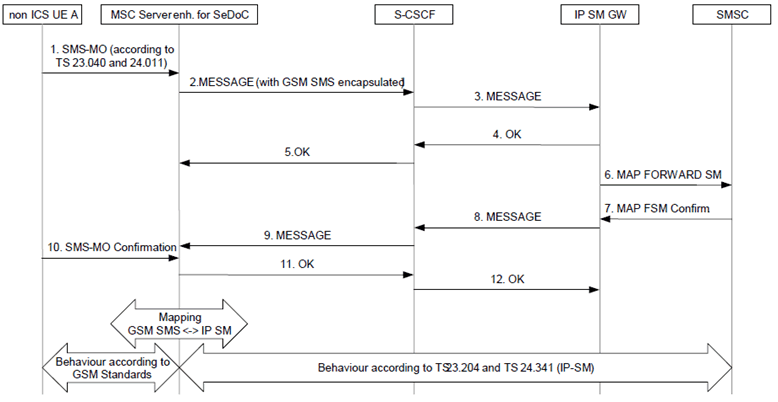
Step 1.
UE submits the standard CS Short Message (as described in TS 23.040and TS 24.011) to the MSC Server enhanced for SeDoC.
Step 2.
MSC Server enhanced for SeDoC encapsulates the Short Message (SMS-SUBMIT, SC Address) and submits it to the S-CSCF using an appropriate SIP method (as described in TS 23.204and TS 24.341).
Step 3.
S-CSCF forwards the encapsulated Short Message (SMS- SUBMIT, SC Address) to IP-SM-GW (AS) based on stored iFC.
Step 4.
IP-SM-GW (AS) acknowledges the SIP message.
Step 5.
SIP message acknowledge is forwarded by S-CSCF to MSC Server enhanced for SeDoC.
Step 6.
The IP-SM-GW performs service authorization based on the stored subscriber data. The IP SM GW checks whether the subscriber is authorised to use the short message service. The IP-SM-GW (AS) extracts the Short Message (SMS- SUBMIT) and forwards it towards the SMS-SC (SC Address) using standard MAP or Diameter based (SGd/Gdd) signalling (as described in TS 23.040).
Step 7.
The SMS-SC sends a Submit report (SMS-SUBMIT REPORT) to IP-SM-GW (AS) (see TS 23.040).
Step 8.
IP-SM-GW (AS) sends the Submit report to S-CSCF, encapsulated in an appropriate SIP request.
Step 9.
The S-CSCF sends the encapsulated Submit report to the MSC Server enhanced for SeDoC.
Step 10.
MSC Server enhanced for SeDoC sends the Submit report to the UE.
Step 11.
The MSC Server enhanced for SeDoC acknowledges the SIP request.
Step 12.
The S-CSCF acknowledges the SIP request.