Content for TS 23.292 Word version: 18.0.0
1…
4…
5…
7…
7.2…
7.3…
7.3.2.2…
7.3.2.2.4…
7.4…
7.4.2.2…
7.4.2.2.3…
7.4.2.2.7…
7.5…
7.6…
7.6.1.2.2.6…
7.6.1.2.3…
7.6.1.2.3.5…
7.6.1.2.3.6…
7.6.2…
7.6.2.7
7.6.2.8…
7.6.2.11…
7.6.3…
7.7…
7.7.2…
7.9…
7.9.2…
7.9.2.4
7.9.2.5
8…
A…
G…
H…
H.5…
H.5.3…
7.6 Consistency of Supplementary Services
7.6.0 General
7.6.1 Supplementary Services for ICS UE
7.6.1.1 Overview
7.6.1.2 IMS sessions using CS bearer
7.6.1.2.1 Overview
7.6.1.2.2 Use of Gm reference point
7.6.1.2.2.1 Line ID Services (OIP, OIR, TIP, TIR)
7.6.1.2.2.2 Communication Diversion Services
7.6.1.2.2.3 Communication Barring
7.6.1.2.2.4 Communication Hold/Resume
7.6.1.2.2.5 Explicit Communication Transfer
7.6.1.2.2.5.1 Consultative ECT using Gm reference point, ICS UE as transfer recipient
7.6.1.2.2.5.2 Blind ECT using Gm reference point, ICS UE as transfer recipient
...
...
7.6 Consistency of Supplementary Services p. 61
7.6.0 General |R10| p. 61
The applicability of Supplementary Services to the different media types that apply for ICS (as defined in clause 22.4 of TS 22.101) are specified in Annex A of TS 22.004.
7.6.1 Supplementary Services for ICS UE p. 61
7.6.1.1 Overview p. 61
When the IP-CAN is used for the media of the IMS session, IMS procedures as defined in TS 24.173 apply for IMS services.
When the CS bearer is used for the media of the IMS session, the Gm or the I1 reference point is used for communication of service control signalling; IMS services are provided to the ICS UE with the IUA of the SCC AS combining the service control signalling with the description of the CS bearer for execution of service control over the Remote Leg.
7.6.1.2 IMS sessions using CS bearer p. 62
7.6.1.2.1 Overview p. 62
When the CS bearer is used for the media of the IMS Multimedia Telephony service, see TS 22.173, the procedures specified in this clause apply.
7.6.1.2.2 Use of Gm reference point p. 62
7.6.1.2.2.1 Line ID Services (OIP, OIR, TIP, TIR) p. 62
IMS procedures as defined in TS 24.173 apply with the SCC AS combining the description of the CS bearer with the service control signalling communicated over the Gm reference point as specified in clause 7.1.
7.6.1.2.2.2 Communication Diversion Services p. 62
IMS procedures as defined in TS 24.173 apply with the IUA of the SCC AS combining the description of the CS bearer with the service control signalling communicated over the Gm reference point as specified in clause 7.1.
7.6.1.2.2.3 Communication Barring p. 62
IMS procedures as defined in TS 24.173 apply with the SCC AS combining the description of the CS bearer with the service control signalling communicated over the Gm reference point as specified in clause 7.1.
7.6.1.2.2.4 Communication Hold/Resume p. 62
IMS procedures as defined in TS 24.173 apply with the SCC AS combining the description of the CS bearer with the service control signalling communicated over the Gm reference point as specified in clause 7.1.
Additionally, the SCC AS may employ an MRF for control of media as needed for execution of the Communication Hold/Resume.
During communication hold, if a held session is resumed with the same service type/bearer requirement (i.e. voice or video) as the existing CS bearer, the CS bearer shall be reused; otherwise, the CS bearer shall be updated if possible through SCUDIF or redial mechanism (refer to clause 7.9).
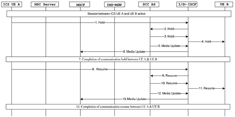
Figure 7.6.1.2.2.4-1 provides the ICS Communication Hold/Resume flow over Gm reference point for the ICS UE.

Figure 7.6.1.2.2.4-1: ICS Communication Hold/Resume over Gm reference point
(⇒ copy of original 3GPP image)
(⇒ copy of original 3GPP image)
Step 1.
The ICS UE A sends a Hold request to the S-CSCF as specified in TS 23.228 and TS 24.173. The hold request indicates whether the media shall continue to be sent to the remote party or not.
Step 2.
The S-CSCF forwards the Hold request to the SCC AS based upon filter criteria.
Step 3.
The SCC AS sends the Hold request to the S-CSCF indicating the remote party shall stop sending the media and, according to the hold request, continue or stop receiving media from the invoking UE.
Step 4.
The S-CSCF sends the Hold request to UE B.
Step 5.
The SCC AS sends a media update request to the S-CSCF indicating the media is held.
Step 6.
The S-CSCF forwards the media update request to the MGCF. Depending on what information is exactly contained in the request, MGCF could send call hold request towards the CS network according to TS 29.163. If the ICS UE A receives this request from MGCF, it shall ignore it.
Step 7.
Completion of communication hold between UE A and UE B based on the procedures specified in TS 23.228.
Step 8.
Step 9.
The S-CSCF forwards the Resume request to the SCC AS based upon filter criteria.
Step 10.
The SCC AS sends the Resume request to the S-CSCF.
Step 11.
The S-CSCF sends the Resume request to UE B.
Step 12.
The SCC AS sends a media update request to the S-CSCF indicating the media is resumed.
Step 13.
The S-CSCF forwards the media update request to the MGCF.
Step 14.
Completion of communication resume between UE A and UE B based on the procedures specified in TS 23.228.
7.6.1.2.2.5 Explicit Communication Transfer p. 64
IMS procedures as defined in TS 24.173 apply with the SCC AS combining the description of the CS bearer with the service control signalling communicated over the Gm reference point as specified in clause 7.1 of this document.
Additionally, the SCC AS may employ an MRF for control of media as needed for execution of the Explicit Communication Transfer.
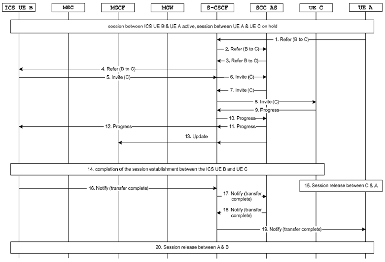
Figure 7.6.1.2.2.5.1-1 describes how IMS consultative ECT is performed when ICS UE B is playing the role of transfer recipient using Gm interface. The UE A has a held call with UE C and an ongoing call with ICS UE B before transfer.

Figure 7.6.1.2.2.5.1-1: IMS Consultative ECT via Gm for ICS UE (transfer recipient)
(⇒ copy of original 3GPP image)
(⇒ copy of original 3GPP image)
Step 1.
UE A initiates transfer of ICS UE B to UE C by sending a REFER request as specified in TS 24.173.
Step 2.
The S-CSCF sends the REFER to the SCC AS as it was inserted at session establishment.
Step 3.
The SCC AS sends the REFER to the S-CSCF.
Step 4.
The S-CSCF sends the REFER to the ICS UE B.
Step 5.
The ICS UE B initiates session establishment towards UE C by initiating an INVITE message.
Step 6.
Filter criteria directs the S-CSCF to send the INVITE to the SCC AS.
Step 7.
The INVITE is sent to the S-CSCF.
Step 8.
The S-CSCF routes the request to UE C.
Step 9.-12.
UE C sends back session progress messages to the ICS UE B via S-CSCF and SCC AS.
Step 13.
SCC AS sends a backward message to MGCF to update MGW port for connecting with UE C.
Step 14.
A session is established between the ICS UE B and UE C.
Step 15.
UE C release the session with UE A.
Step 16.
The ICS UE B provides indication that the communication transfer is complete by sending a NOTIFY message as specified in TS 24.173.
Step 17.
The S-CSCF sends the NOTIFY to the SCC AS as it was inserted at session establishment.
Step 18.
The SCC AS sends the NOTIFY to the S-CSCF.
Step 19.
The NOTIFY is sent to UE A.
Step 20.
The UE A initiates session release with ICS UE B and release the session.
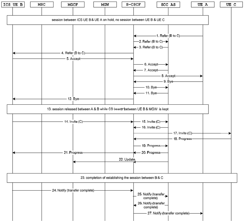
Figure 7.6.1.2.2.5.2-1 describes how IMS blind ECT is performed when ICS UE is playing the role of transfer recipient using Gm interface. The UE A has a held call with ICS UE B and no session with UE C before transfer.
Additionally, the SCC AS may employ an MRF for control of media as needed for execution of the Communication ECT.

Figure 7.6.1.2.2.5.2-1: IMS blind ECT via Gm for ICS UE (transfer recipient)
(⇒ copy of original 3GPP image)
(⇒ copy of original 3GPP image)
Step 1.
UE A initiates transfer of ICS UE B to UE C by sending a REFER as specified in TS 24.173.
Step 2.
The S-CSCF sends the REFER to the SCC AS as it was inserted at session establishment.
Step 3.
The SCC AS acknowledges the REFER message as a blind transfer request for ICS UE B and sends the REFER to the S-CSCF.
Step 4.
The S-CSCF sends the REFER to the ICS UE B.
Step 5.
ICS UE B accepts the transfer request.
Step 6.
The S-CSCF sends the accept message to the SCC AS as it was inserted at session establishment.
Step 7.
The SCC AS sends the accept message to the S-CSCF.
Step 8.
The S-CSCF sends the accept message to the UE A.
Step 9.
On reception of the accept message from the ICS UE B, UE A initiates the session release with the ICS UE B by initiating a BYE message to ICS UE B.
Step 10.
The S-CSCF sends the BYE to the SCC AS as it was inserted at session establishment. On reception of the BYE, the SCC AS releases only the PS session signalling path with UE A and keeps the CS bearer between ICS UE B and the MGW.
Step 11.
The SCC AS sends the BYE to the S-CSCF.
Step 12.
The S-CSCF sends the BYE to the ICS UE B.
Step 13.
Session between UE A and ICS UE B is released. The CS bearer from ICS UE B and MGW is kept for further reuse.
Step 14.
The ICS UE B initiates session establishment towards UE C by initiating an INVITE message.
Step 15.
Filter criteria directs the S-CSCF to send the INVITE to the SCC AS.
Step 16.
The INVITE with the MGW SDP received from the MSC Server/ MGCF upon UE A-UE B session establishment is sent to the S-CSCF.
Step 17.
The S-CSCF routes the request onwards to UE C.
Step 18.-21.
UE C sends back session progress messages to the ICS UE B via S-CSCF and SCC AS.
Step 22.
SCC AS sends a backward message to MGCF to update the MGW port for connecting with UE C.
Step 23.
A session is established between the ICS UE B and UE C.
Step 24.
The ICS UE B provides indication that the communication transfer is complete by sending a NOTIFY as specified in TS 24.173.
Step 25.
The S-CSCF sends the NOTIFY to the SCC AS as it was inserted at session establishment.
Step 26.
The SCC AS sends the NOTIFY to the S-CSCF.
Step 27.
The NOTIFY is sent to UE C as specified in TS 24.173.