Content for TS 23.292 Word version: 18.0.0
1…
4…
5…
7…
7.2…
7.3…
7.3.2.2…
7.3.2.2.4…
7.4…
7.4.2.2…
7.4.2.2.3…
7.4.2.2.7…
7.5…
7.6…
7.6.1.2.2.6…
7.6.1.2.3…
7.6.1.2.3.5…
7.6.1.2.3.6…
7.6.2…
7.6.2.7
7.6.2.8…
7.6.2.11…
7.6.3…
7.7…
7.7.2…
7.9…
7.9.2…
7.9.2.4
7.9.2.5
8…
A…
G…
H…
H.5…
H.5.3…
7.6.1.2.3 Use of I1 reference point
7.6.1.2.3.1 Line ID Services (OIP, OIR, TIP, TIR)
7.6.1.2.3.2 Communication Diversion Services
7.6.1.2.3.2.1 Communication Forwarding Unconditional (CFU)
7.6.1.2.3.2.2 Communication Forwarding on Not Logged-in (CFNL)
7.6.1.2.3.2.3 Communication Forwarding Busy (CFB)
7.6.1.2.3.2.4 Communication Forwarding No Reply (CFNR)
7.6.1.2.3.2.5 Communication Forwarding on Subscriber Not Reachable (CFNRc)
7.6.1.2.3.2.6 Communication Deflection (CD)
7.6.1.2.3.2.7 Communication Diversion Notification (CDIVN)
7.6.1.2.3.3 Communication Barring
7.6.1.2.3.4 Communication Hold/Resume
...
...
7.6.1.2.3 Use of I1 reference point |R9| p. 70
7.6.1.2.3.1 Line ID Services (OIP, OIR, TIP, TIR) p. 70
IMS procedures as defined in TS 24.173 apply. The SCC AS combines the description of the CS bearer with the service control signalling communicated over the I1 reference point, as specified in clause 7.1 of this document. The information specific to Line ID services is communicated over the I1 reference point when the I1 reference point is used at session setup.
7.6.1.2.3.2 Communication Diversion Services p. 70
IMS procedures as defined in TS 24.173 apply. The SCC AS combines the description of the CS bearer with the service control signalling communicated over the I1 reference point, as specified in clause 7.1.
IMS procedures as defined in TS 24.173 apply. The SCC AS combines the description of the CS bearer with the service control signalling communicated over the I1 reference point, as specified in clause 7.1.
IMS procedures as defined in TS 24.173 apply. The SCC AS combines the description of the CS bearer with the service control signalling communicated over the I1 reference point, as specified in clause 7.1. When I1 is used for session set-up, the information specific to CFB is communicated over the I1 reference point; the SCC AS performs the necessary interworking between the I1 signalling and IMS to allow execution of CFB in IMS.
Figure 7.6.1.2.3.2.3-1 provides the Communication Forwarding Busy (CFB) flow over the I1 reference point for an ICS UE.
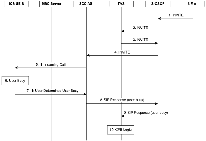
Figure 7.6.1.2.3.2.3-1: Communication Forwarding on Busy User flow over the I1 reference point for an ICS UE
(⇒ copy of original 3GPP image)
(⇒ copy of original 3GPP image)
Step 1.
An incoming SIP INVITE is received at the S-CSCF of the B party from the A party.
Step 2-4.
The S-CSCF forwards the INVITE to the TAS and SCC AS.
Step 5.
The SCC AS sends an incoming Call Request to the UE over I1 via the MSC server.
Step 6-7.
The UE rejects the incoming call request as the user is busy and sends a User Determine User Busy (UDUB) response over I1 to the SCC AS.
Step 8-9.
The SCC AS inter-works the UDUB response over I1 into an appropriate SIP Response to indicate that the B party is busy, and sends the SIP Response to the TAS via the CSCF.
Step 10.
The TAS processes the SIP Response and executes the CFB logic.
IMS procedures as defined in TS 24.173 apply. The SCC AS combines the description of the CS bearer with the service control signalling communicated over the I1 reference point, as specified in clause 7.1. The information specific to CFNR is communicated over the I1 reference point when the I1 reference point is used at session setup.
Figure 7.6.1.2.3.2.4-1 provides the Communication Forwarding No Reply flow over the I1 reference point for an ICS UE.
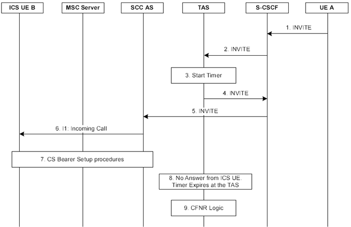
Figure 7.6.1.2.3.2.4-1: Communication Forwarding No Reply flow over the I1 reference point for an ICS UE
(⇒ copy of original 3GPP image)
(⇒ copy of original 3GPP image)
Step 1.
An incoming SIP INVITE is received at the S-CSCF of the B party from the A party.
Step 2.
The S-CSCF forwards the INVITE to the TAS and SCC AS.
Step 3.
The SCC AS starts a supervisory timer for the call.
Step 4-5.
The TAS forwards the INVITE to the SCC AS via the S-CSCF.
Step 6.
The SCC AS sends an incoming Call Request to the ICS UE over I1.
Step 7.
The ICS UE performs CS bearer set-up procedures.
Step 8.
The SCC AS does not receive an answer from the ICS UE and the timer at the TAS expires.
Step 9.
The TAS executes the CFNR logic.
IMS procedures as defined in TS 24.173 apply. The SCC AS combines the description of the CS bearer with the service control signalling communicated over the I1 reference point, as specified in clause 7.1. When I1 is used for call set-up, the SCC AS performs the necessary interworking between the I1 signalling response and SIP to allow execution of CFNRc in IMS.
Figure 7.6.1.2.3.2.5-1 provides the Communication Forwarding on Subscriber Not Reachable flow over the I1 reference point for an ICS UE.
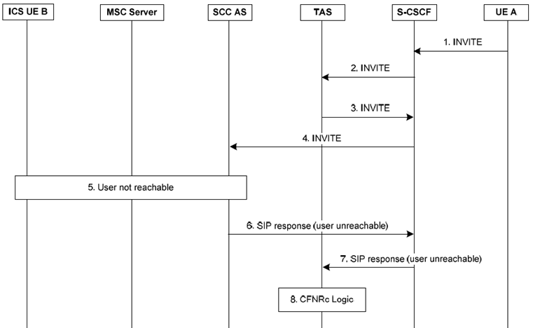
Figure 7.6.1.2.3.2.5-1: Communication Forwarding Not Reachable flow over the I1 reference point for an ICS UE
(⇒ copy of original 3GPP image)
(⇒ copy of original 3GPP image)
Step 1.
An incoming SIP INVITE is received at the S-CSCF of the B party from the A party.
Step 2-4.
The S-CSCF forwards the INVITE to the TAS and SCC AS.
Step 5.
The SCC AS, MSC Server or another node in the Service Control Signalling Path (e.g. HSS or HLR) determines that the user is not reachable, for example:
Step 6-7.
- The MSC Server pages the ICS UE B and no response to the page message is received.
- The MSC Server itself determines that the user is not reachable (e.g. IMSI detach).
- The MSC Server pages the ICS UE B and a page response is received but the CS bearer set up procedures fail.
The SCC AS sends an appropriate SIP response that indicates that the user is unreachable to the TAS via the CSCF.
Step 8.
The TAS processes the SIP response and executes the CFNRc logic.
IMS procedures as defined in TS 24.173 apply. The SCC AS combines the description of the CS bearer with the service control signalling communicated over the I1 reference point, as specified in clause 7.1. When I1 is used for call set-up, the information specific to CD is communicated over the I1 reference point; the SCC AS performs the necessary interworking between the I1 signalling and SIP to allow execution of CD in IMS.
Figure 7.6.1.2.3.2.6-1 provides the Communication Deflection (CD) flow over the I1 reference point for an ICS UE.
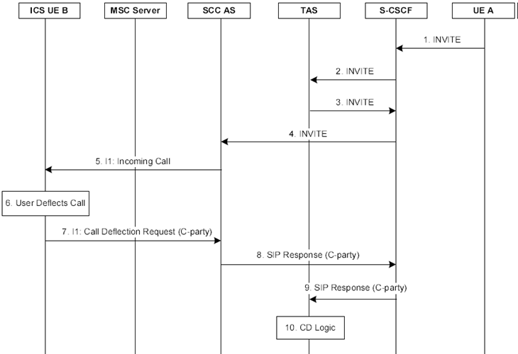
Figure 7.6.1.2.3.2.6-1: Communication Deflection flow over the I1 reference point for an ICS UE
(⇒ copy of original 3GPP image)
(⇒ copy of original 3GPP image)
Step 1.
An incoming SIP INVITE is received at the S-CSCF of the B party from the A party.
Step 2-4.
The S-CSCF forwards the INVITE to the TAS and SCC AS.
Step 5.
The SCC AS sends an incoming Call Request to the UE over I1 via the MSC server.
Step 6-7.
The user decides to deflect the call and the UE returns a Call Deflection Request to the SCC AS over I1 indicating the deflected-to party.
Step 8-9.
The SCC AS inter-works the Call Deflection Request received over I1 into an appropriate SIP response and sends the SIP response to the TAS via the CSCF.
Step 10.
The TAS processes the SIP response and executes the CD logic.
IMS procedures as defined in TS 24.173 apply. The SCC AS combines the description of the CS bearer with the service control signalling communicated over the I1 reference point, as specified in clause 7.1.
When I1 is used for call set-up, the SCC AS performs the necessary interworking between the I1 signalling and SIP to subscribe to the comm-div-info event package at the TAS on behalf of the UE and to receive and propagate to the UE, the notification that the call was diverted.
7.6.1.2.3.3 Communication Barring p. 74
IMS procedures as defined in TS 24.173 apply. The SCC AS combines the description of the CS bearer with the service control signalling communicated over the I1 reference point, as specified in clause 7.1.
7.6.1.2.3.4 Communication Hold/Resume p. 75
IMS procedures as defined in TS 24.173 apply. The SCC AS combines the description of the CS bearer with the service control signalling communicated over the I1 reference point, as specified in clause 7.1 of this document.
Additionally, the SCC AS may employ an MRF for control of media as needed for execution of the Communication Hold/Resume.
During communication hold, if a held session is resumed with the same service type/bearer requirement (i.e. voice or video) as the existing CS bearer, the CS bearer shall be reused; otherwise, the CS bearer shall be updated if possible through SCUDIF or redial mechanism (refer to clause 7.9).
Figure 7.6.1.2.3.4-1 describes how IMS session hold and resume is performed via I1 interface for ICS UE.
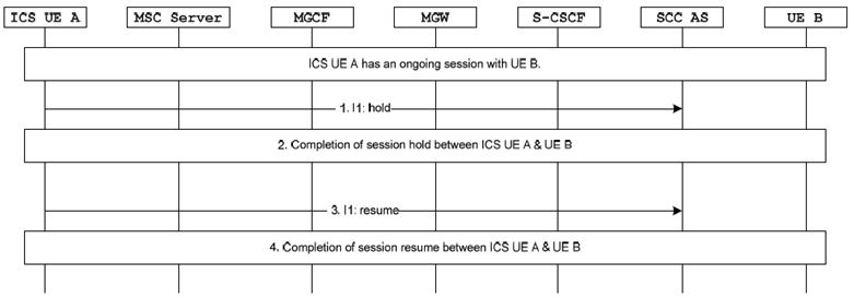
Step 1.
The ICS UE A sends a Hold message to the SCC AS via I1 reference point.
Step 2.
The session between ICS UE A and UE B is held as specified in clause 7.6.1.2.2.4.
Step 3.
The ICS UE A sends a Resume message to the SCC AS via I1 reference point.
Step 4.
The session between ICS UE A and UE B is resumed as specified in clause 7.6.1.2.2.4.