Content for TS 23.236 Word version: 18.0.0
A.3 Support of Dedicated Core Networks |R13| p. 42
An overview of dedicated core network (DCN) feature is provided in TS 23.401. This Annex provides an example of NRI configuration for supporting DCNs.
The following example shows a split of NRI values between operators A (0..99) and B (100..199). Each operator has a separate core network. Furthermore, each operator has two DCNs (A1, A2) and (B1, B2).
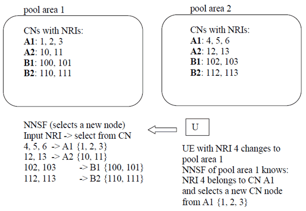
Two pool/deployment areas are shown below.

The Figure above shows how the NNSF of pool 1 is configured to select the same operator and same DCN when a UE moves in from neighbour pool area 2. This configuration avoids redirection procedure for UEs that move in idle mode between the pool areas.
With the NNSF configured above, there are NRIs available that may be re-used for redistribution of UEs within the pool without requiring reservation of extra NRIs for redistribution i.e. the NRI allocated to a neighbouring pool area and not allocated in this pool area may be used as a Null-NRI for the pool area. This also avoids the need for additional configuration in NNSF.
In the example above, all A1 nodes of pool 1 may use NRI 4 as Null-NRI for redistributing UEs between A1 nodes of pool 1. The NNSFs of pool 1 are configured to select a new node from nodes belonging to A1, when a UE indicates an IDNNS with NRI 4 or NRI 4 is provided as the Null-NRI in the NAS message redirection procedure by an SGSN (see TS 23.401).