Content for TS 23.236 Word version: 18.0.0
A Network configuration examples p. 33
A.1 One city centre surrounded by residential areas p. 33
A.1.1 Assumptions p. 33
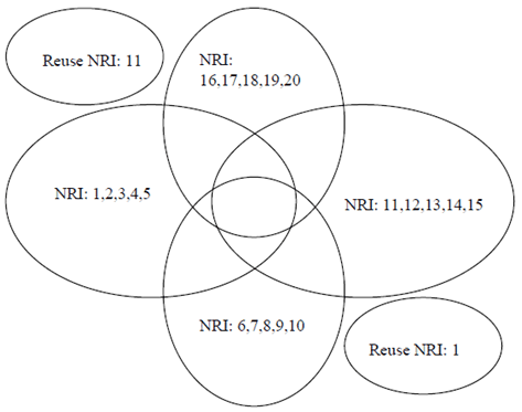
This example shows a network covering one city centre surrounded by residential areas. The city centre is covered by all 4 pool-areas while the residential areas are covered by one pool-area only. Once a subscriber "found" its pool-area, he will not change the pool-area while commuting between the city centre and his residential area.
Each of the pool-areas is served by 5 MSCs, indicated by the 5 NRI values in the Figure below.
The example in the Figure configures 4 overlapping pool-areas:
- City centre with 12 Mio subscribers (with context in VLR, attached or detached);
- One switch office/building with 5 MSCs (5 NRIs) per pool-area;
- Capacity of one MSC/VLR up to 1 Mio subscribers in VLR;
- 4 bits are assumed for the VLR-restart counter;
- Only distinct NRI values are used, so a UE changing between pool-areas will always be allocated to a new MSC by the NAS node selection function.

A.1.2 TMSI calculation p. 33
For addressing in the CS domain 30 bits for can be used (Bit 30&31 are reserved):
- The assumption is that 4 bits are used for the restart counter;
- To differentiate the 20 MSC in the city area 5 bits are needed for the NRI (12 NRI values remain unused; these 12 NRIs are left for additional MSCs in the whole area, NRIs can also be re-used as indicated in the Figure);
- This leaves 30-4-5 = 21 bits for every MSC to address the subscriber data records in the VLR. (This give address space for 2 Mio TMSIs unique over all LAs of the MSC);
- The 4 pool-areas sum up to 20 Mio subscriber, allowing for some unbalanced load distribution.