Content for TS 23.236 Word version: 18.0.0
6 Application Examples p. 20
This clause describes some application examples for networks using the intra domain NAS node selection. In these examples, pool-areas are depicted by boxes or ellipses, while the core network elements which serve the pool-areas are depicted by the NRIs they have been assigned.
6.1 Network configuration example 1 p. 20
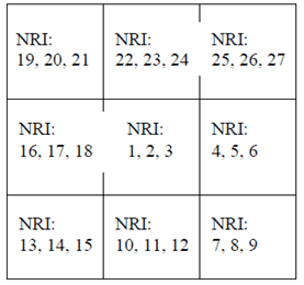
This example configures 9 pool-areas each with 3 CN nodes serving within a pool-area. When a MS moves from one (NRI:1,2,3) to another pool-area (NRI:4,5,6). It indicates the old NRI (3) derived from its old TMSI to the RNC in the new pool-area (NRI:4,5,6). This NRI 3 is not configured in the RNC of the pool-area (NRI:4,5,6). The RNC selects a CN node out of the available NRIs 4,5,6 and establishes the signalling connection for the MS with the selected CN node. This new CN nodes allocates a new TMSI to the MS and thereby the new NRI for the new pool-area.
In this example, the NRIs can be re-used in a pattern where adjacent pool areas do not use the same NRI. Every pool area change will initiate a new selection of a new CN node.

6.2 Network configuration example 2 p. 20
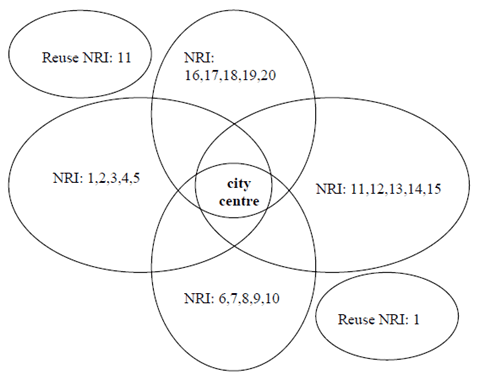
This example shows a network covering one city centre surrounded by residential areas. The city centre is covered by all 4 pool-areas while each of the residential areas is covered by one pool-area only. Once a MS "found" its pool-area, it will not change the pool-area while commuting between the city centre and its residential area. Each of the pool-areas is served by 5 MSCs, indicated by the 5 NRI values in the Figure below, which share the load within the pool-area. Only distinct NRI values are used for the overlapping pool-areas. Therefore, a MS changing between these pool-areas will always be allocated to a new MSC by the NAS node selection function. In addition it is shown, that the NRIs can be re-used in other pool-areas as indicated in the Figure by the smaller areas with only one NRI. Also at a change to these areas the MSs will always be allocated to a new MSC by the NAS node selection function as adjacent areas do not use the same NRI values.
A calculation for the possible number of subscribers in this scenario is in Annex A.1: One city centre surrounded by residential areas
