Content for TS 23.236 Word version: 18.0.0
4 General Description
4.1 Iu Flex Technical Requirements
4.2 Overview
4.3 Pool-Area and Network Resource Identification
4.4 NAS Node Selection Function
...
...
4 General Description p. 8
4.1 Iu Flex Technical Requirements p. 8
This provides a (non-exhaustive) set of technical requirements:
- Iu Flex capable RAN nodes such as the RNC/BSC shall be able to select any CN node such as the SGSN/MSC-Server within a pool area
- Iu Flex capable RAN nodes and CN nodes shall be able to co-exist with pre Release 5 RAN nodes and pre Release 5 CN nodes.
- The network shall provide the CN node routing information to the UE and the UE shall store it.
- The UE shall provide the routing information received from the serving CN node to the RAN node. In some cases, this serving CN node may be an Evolved Packet Core MME.
- The solution shall enable the reduction of signalling within the core network (e.g. reduction of the HLR signalling traffic).
- The solution shall enable an improved scaling between radio access nodes and the core network nodes.
4.2 Overview p. 8
4.3 Pool-Area and Network Resource Identification p. 10
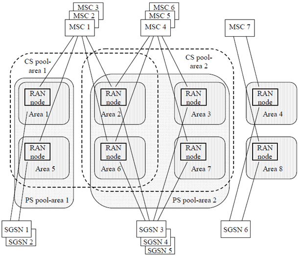
A pool-area is an area within which an MS may roam without a need to change the serving CN node. A pool-area is served by one or more CN nodes in parallel. The complete service area of a RAN node (RNC or BSC) belongs to the same one or more pool-area(s). A RAN node service area may belong to multiple pool-areas, which is the case when multiple overlapping pool-areas include this RAN node service area. The pool-areas of the CS and of the PS domain are configured independently with the granularity of RAN node service areas. Therefore, all uniqueness statements below apply to each of the domains (CS/PS) separately. If LAs or RAs span over multiple RAN node service areas then all these RAN node service areas have to belong to the same pool-area.
The Network Resource Identifier (NRI) identifies uniquely an individual CN node out of all CN nodes, which serve in parallel a pool-area. The length of the NRI shall be the same in all nodes of a domain in one pool-area. In areas where pool-areas overlap the NRI identifies uniquely a CN node out of all CN nodes, which serve all these overlapping pool-areas, i.e. an NRI identifies uniquely a CN node within a RAN node. In case of overlapping pool-areas the NRI length shall be configured to be the same in all the nodes of a specific domain serving these pool-areas. Note again, that the NRIs of the CS and the PS domain are independent of each other as the PS and the CS domain CN nodes are addressed independently. More than one NRI may be assigned to a CN node.
The NRI is part of the temporary identity TMSI (CS domain) or P-TMSI (PS domain), which is assigned by the serving CN node to the MS. Each CN node which supports the "Intra Domain Connection of RAN Nodes to Multiple CN Nodes" is configured with its specific one or more NRI(s). The (P-)TMSI allocation mechanism in the CN node generates (P-)TMSIs which contain a configured NRI in the relevant bit positions. The NRI has a flexible length between 10 and 0 bits (0 bits means the NRI is not used and the feature is not applied).
In Iu mode the MS provides an Intra Domain NAS Node Selector (IDNNS) TS 25.331 in the AS part of the RRC-Initial-direct-transfer message to the RAN node (RNC or BSC). The IDNNS contains a routing parameter with a fixed length of 10 bits. This routing parameter transports the NRI value. In addition the IDNNS contains an indication from which identity (TMSI, IMSI, IMEI, ...) the routing parameter is derived. The RAN node masks the significant bits out of the routing parameter part of the IDNNS to determine the NRI which is relevant to identify the CN node. The most significant bit of the NRI shall correspond with the most significant bit of the routing parameter in the IDNNS. When the IDNNS is derived from the IMSI, the IDNNS has a value (V) from the range 0 to 999 as defined in TS 25.331. The RAN node shall be configured to use the value (V) to select a CN node. Each value (V) corresponds a single CN node. Typically many values of (V) may point to the same CN node. In A/Gb mode.
In A/Gb-mode for the A interface the RAN node derives the NRI from any initial NAS signalling message. The RAN node masks the significant bits out of the TMSI to determine the NRI, which identifies the CN node. In A/Gb-mode for the Gb interface the RAN node derives the NRI from the TLLI. The RAN node masks the significant bits out of the TLLI to determine the NRI, which identifies the CN node.
For all three cases, Iu, A interface and Gb mode, it is configured in the RAN node which bits out of the information elements provided by the MS are significant for the NRI The NRI is coded in bits 23 to 14 of TMSI or P-TMSI. Regardless of the NRI length the most significant bit of the NRI is always in bit 23 of TMSI or P-TMSI(examples of NRI position are given in Annex A.2), see also TS 23.003.
The whole network may be configured as one pool-area, a network may configure multiple pool-areas and the configuration of pool-areas may be combined with MSC or SGSN service areas which are not belonging to pool-areas. The change of a pool-area is not visible to the MS. In general there is no need to detect a pool-area change. It may be advantageous for load balancing purposes to detect pool-area changes in the network to distribute MSs entering a pool-area to CN nodes with an appropriate load status. MSs changing a pool-area may be detected by configuration of different NRI values for adjacent pool-areas. The pool-area change information potentially provided in the IDNNS by an MS in Iu mode is ignored by the network.
4.4 NAS Node Selection Function p. 10
This function is used in RAN nodes and potentially in CN nodes. In the RAN node the function selects the specific CN node (i.e. MSC or SGSN) to which initial NAS signalling messages or LLC frames are routed. The NRI identifies the specific CN node. If the NAS Node Selection Function has a CN node address configured for the NRI derived from the initial NAS signalling message or from the LLC frame then this message or frame is routed to this address. If no CN node address is configured for the derived NRI or if no NRI can be derived (e.g. the MS indicated an identity which contains no NRI) then the NAS Node Selection Function selects an available CN node (e.g. according to load balancing) and routes the message or LLC frame to the selected CN node.
The pool-area has no influence on the decisions of the NAS Node Selection Function as pool-areas may overlap. The NAS Node Selection Function in the RAN node derives the NRI from the IDNNS when the MS is supported in Iu mode. When the MS is supported in Gb mode the NRI is derived from the TLLI and for A interface mode the NRI is derived from the TMSI.
In A/Gb mode in case a MSC/VLR sends a paging-request/paging with IMSI (i.e. the paging message does not contain a TMSI), the NAS node selection function in the BSC shall upon reception temporarily store the Global-CN- ID of the node that issued the paging-request/paging message. If the NAS node selection function in A/Gb mode receives a paging-response with an IMSI then it should check the temporarily stored Global-CN-ID on entries matching this IMSI and forward the paging-response to the node identified by this Global-CN-ID.
In Iu mode in case a MSC/VLR sends a paging-request/paging with IMSI (i.e. the paging message does not contain a TMSI), the NAS node selection function in the BSC/RNC may upon reception temporarily store the Global-CN-ID of the node that issued the paging-request/paging message. If the NAS node selection function in Iu mode receives an Initial Direct Transfer message with an IDNNS derived from IMSI as a result of IMSI paging:
- and if BSC/RNC has temporarily stored the Global-CN-ID then it should check the temporarily stored Global-CN-ID on entries matching this IDNNS and forward the paging-response to the node identified by this Global-CN-ID or
- the BSC/RNC shall use the IDNNS derived from IMSI to select a CN node. In this case the IDNNS has a value (V) from the range 0 to 999 as defined in TS 25.331. The RAN node shall be configured to use the value (V) to select a CN node. Each value (V) corresponds a single CN node. Typically many values of (V) may point to the same CN node.
![]()
![]()
![]()