Content for TS 23.236 Word version: 18.0.0
7.3 Signalling flows for Service Request (Iu interface mode)
7.3.1 Service Request initiated by MS
7.3.2 Service Request initiated by network
...
...
7.3 Signalling flows for Service Request (Iu interface mode) p. 24
When performing service request, the signalling connection between the MS and the SGSN is re-established.
7.3.1 Service Request initiated by MS p. 24
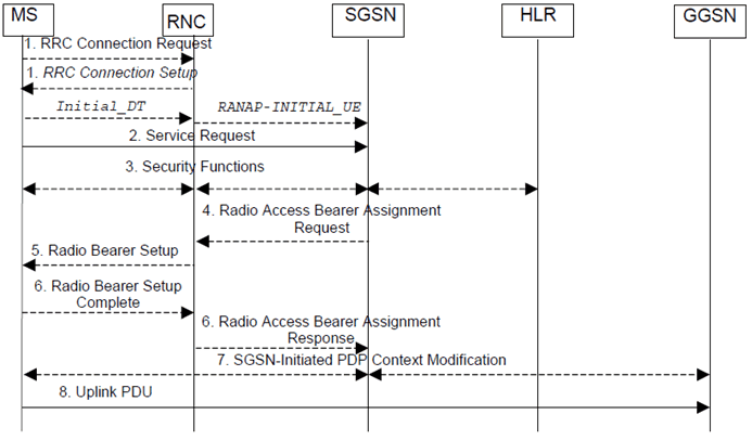
The service request procedure initiated by the MS is shown in the Figure below.

Figure 5: Signalling flows for Service Request initiated by MS (Iu interface mode)
(⇒ copy of original 3GPP image)
(⇒ copy of original 3GPP image)
Step 1.
The MS establishes an RRC connection, if none exists for CS traffic.
Step 2.
The MS sends a Service Request (P-TMSI, RAI, CKSN, Service Type) message to the SGSN. Service Type specifies the requested service. Service Type shall indicate one of the following: Data or Signalling. The Service Request is carried in the Initial Direct Transfer message (RRC) from the MS to the RNC. The RNC selects an SGSN to serve the MS as described in clause 7.1.3 and relays the Service Request to the SGSN in the Initial UE message (RANAP). At this point, the SGSN may perform the authentication procedure.
Step 3.
- If Service Type indicates Data, a signalling connection is established between the MS and the SGSN, and resources for active PDP context(s) are allocated, i.e., RAB establishment for the activated PDP context(s).
- If Service Type indicates Signalling, the signalling connection is established between the MS and the SGSN for sending upper-layer signalling messages, e.g., Activate PDP Context Request. The resources for active PDP context(s) are not allocated.
The SGSN shall perform the security functions if the MS in PMM-IDLE state initiated the service request.
Step 4.
If the network is in PMM-CONNECTED state and the Service Type indicates Data, the SGSN shall respond with a Service Accept message towards the MS, in case the service request can be accepted. In case Service Type indicates Data, the SGSN sends a Radio Access Bearer Assignment Request (NSAPIRAB ID(s), TEID(s), QoS Profile(s), SGSN IP Address(es)) message to re-establish radio access bearer for every activated PDP context.
Step 5.
The RNC indicates to the MS the new Radio Bearer Identity established and the corresponding RAB ID with the RRC radio bearer setup procedure.
Step 6.
SRNC responds with the Radio Access Bearer Assignment Response (RAB ID(s), TEID(s), QoS Profile(s), RNC IP Address(es)) message. The GTP tunnel(s) are established on the Iu interface. If the RNC returns a Radio Access Bearer Assignment Response message with a cause indicating that the requested QoS profile(s) can not be provided, e.g., "Requested Maximum Bit Rate not Available", the SGSN may send a new Radio Access Bearer Assignment Request message with different QoS profile(s). The number of re-attempts, if any, as well as how the new QoS profile(s) values are determined is implementation dependent.
Step 7.
For each RAB re-established with a modified QoS profile, the SGSN initiates a PDP Context Modification procedure to inform the MS and the GGSN of the new negotiated QoS profile for the corresponding PDP context.
Step 8.
The MS sends the uplink packet.
7.3.2 Service Request initiated by network p. 25
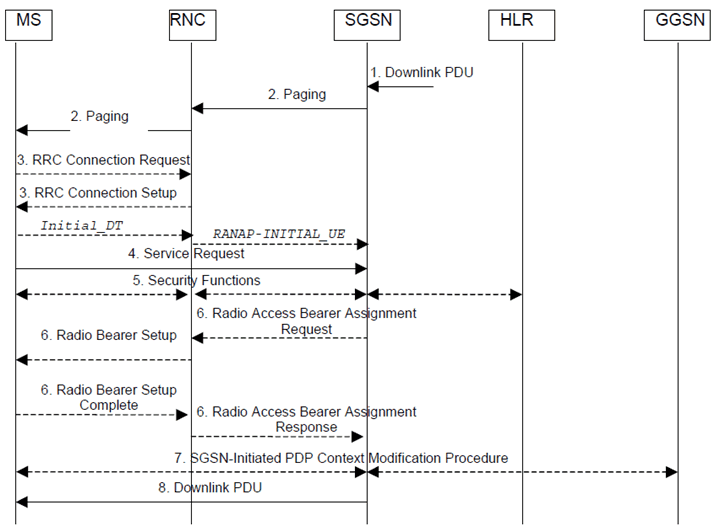
The service request procedure initiated by the network is shown in the Figure below.

Figure 6: Signalling flows for Service Request initiated by network (Iu interface mode)
(⇒ copy of original 3GPP image)
(⇒ copy of original 3GPP image)
Step 1.
The SGSN receives a downlink PDP PDU for an MS in PMM IDLE state.
Step 2.
The SGSN sends a Paging message to the RNC. The RNC pages the MS by sending a Paging message to the MS. See clause "PS Paging Initiated by 3G SGSN without RRC Connection for CS" of TS 23.060 for details.
Step 3.
The MS establishes an RRC connection if none exists for CS traffic.
Step 4.
The MS sends a Service Request (P-TMSI, RAI, CKSN, Service Type) message to the SGSN. Service Type specifies Paging Response. The Service Request is carried over the radio in an RRC Direct Transfer message. The RNC selects an SGSN to serve the MS as described in clause 7.1.3 and relays the Service Request to the SGSN in the Initial UE message (RANAP). At this point, the SGSN may perform the authentication procedure. The SGSN knows whether the downlink packet requires RAB establishment (e.g., downlink PDU) or not (e.g., Request PDP Context Activation or MT SMS).
Step 5.
The SGSN shall perform the security mode procedure.
Step 6.
If resources for the PDP contexts are re-established, the SGSN sends a Radio Access Bearer Assignment Request (RAB ID(s), TEID(s), QoS Profile(s), SGSN IP Address(es)) message to the RNC. The RNC sends a Radio Bearer Setup (RAB ID(s)) to the MS. The MS responds by returning a Radio Bearer Setup Complete message to the RNC. The RNC sends a Radio Access Bearer Assignment Response (RAB ID(s), TEID(s), RNC IP Address(es)) message to the SGSN in order to indicate that GTP tunnels are established on the Iu interface and radio access bearers are established between the RNC and the MS. If the RNC returns a Radio Access Bearer Assignment Response message with a cause indicating that the requested QoS profile(s) can not be provided, e.g., "Requested Maximum Bit Rate not Available", the SGSN may send a new Radio Access Bearer Assignment Request message with different QoS profile(s). The number of re-attempts, if any, as well as how the new QoS profile(s) values are determined is implementation dependent.
Step 7.
For each RAB re-established with a modified QoS profile, the SGSN initiates a PDP Context Modification procedure to inform the MS and the GGSN of the new negotiated QoS profile for the corresponding PDP context.
Step 8.
The SGSN sends the downlink packet.