Content for TS 23.203 Word version: 19.1.0
0…
4…
5…
6…
6.1.4…
6.1.7…
6.1.10…
6.1.17…
6.2…
6.2.2…
6.2.3…
6.3
6.4…
6.8…
7…
7.3…
7.4…
7.7…
7.7.3…
7.8…
A…
A.4…
D…
P…
P.4.2.4…
P.7…
P.7.5…
P.8
Q…
S…
S.7…
S.8.8
T…
7.8 Change in subscription for MPS priority services
7.9 Procedures over Sy reference point
7.9.1 Initial Spending Limit Report Request
7.9.2 Intermediate Spending Limit Report Request
7.9.3 Final Spending Limit Report Request
7.9.4 Spending Limit Report
7.9.5 Sy Session Termination
7.10 Procedures over Np reference point
7.10.1 Report RAN user plane congestion information to PCRF
7.10.2 PCRF provided reporting restrictions
7.10.3 UE mobility between RCAFs
7.11 Procedures over Nt reference point
7.12 Procedures for management of PFDs
...
...
7.8 Change in subscription for MPS priority services |R10| p. 159
Once the PCRF receives a notification of a change in MPS EPS Priority, MPS Priority Level and/or IMS Signalling Priority from the SPR, the PCRF shall make the corresponding policy decisions (i.e. ARP and/or QCI change) and initiates the necessary IP-CAN session modification procedure(s) to apply the change.
7.9 Procedures over Sy reference point |R11| p. 159
7.9.1 Initial Spending Limit Report Request p. 159
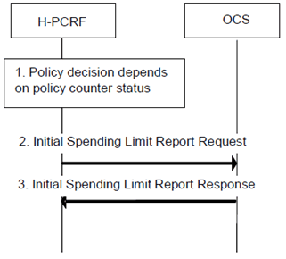
This clause describes the signalling flow for the H-PCRF to request the status of the policy counters available at the OCS and to subscribe to spending limit reporting (i.e. to notifications of policy counter status changes) by the OCS. If the H-PCRF provides the list of policy counter identifier(s), the OCS returns the policy counter status per policy counter identifier provided by the PCRF. If the H-PCRF does not provide the list of policy counter identifier(s), the OCS returns the policy counter status of all policy counter(s), which are available for this subscriber.
The Initial Spending Limit Report Request includes all subscriber Identifiers associated with the UE available at the PCRF.
Step 1.
The H-PCRF retrieves subscription information that indicates that policy decisions depend on the status of policy counter(s) held at the OCS and optionally the list of policy counter identifier(s).
Step 2.
The H-PCRF sends an Initial Spending Limit Report Request if this is the first time policy counter status information is requested for the user and the PDN connection. It includes in the request: the subscriber ID (e.g. IMSI) and , optionally, the list of policy counter identifier(s).
Step 3.
The OCS sends an Initial Spending Limit Report Response that contains a policy counter status and optionally pending policy counter statuses and their activation times, per required policy counter identifier and stores the H-PCRF's subscription to spending limit reports for these policy counters. If no policy counter identifier(s) was provided the OCS returns the policy counter status, optionally including pending policy counter statuses and their activation times, for all policy counter(s), which are available for this subscriber and stores the H-PCRF's subscription to spending limit reports of all policy counters provided to the H-PCRF. Otherwise, the OCS returns the policy counter status of all policy counter(s), which are available for this subscriber.
7.9.2 Intermediate Spending Limit Report Request p. 160
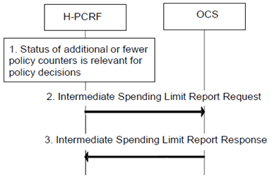
This clause describes the signalling flow for the H-PCRF to request the status of additional policy counters available at the OCS or to unsubscribe from spending limit reporting. If the H-PCRF provides the list of policy counter identifier(s), the OCS returns the policy counter status per policy counter identifier provided by the PCRF.
Step 1.
The H-PCRF determines that policy decisions depend on the status of additional policy counter(s) held at the OCS or that notifications of policy counter status changes for some policy counters are no longer required.
Step 2.
The H-PCRF sends an Intermediate Spending Limit Report Request, optionally including in the request an updated list of policy counter identifier(s).
Step 3.
The OCS sends the Intermediate Spending Limit Report Response that contains the policy counter status and optionally pending policy counter statuses and their activation times, per required policy counter identifier and stores or removes the H-PCRF's subscription to spending limit reporting by comparing the updated list with the existing H-PCRF subscriptions. If no policy counter identifier(s) was provided, the OCS returns the policy counter status, optionally including pending policy counter statuses and their activation times, for all policy counter(s), which are available for this subscriber and stores the H-PCRF's subscription to spending limit reports of all policy counters provided to the H-PCRF.
7.9.3 Final Spending Limit Report Request p. 160
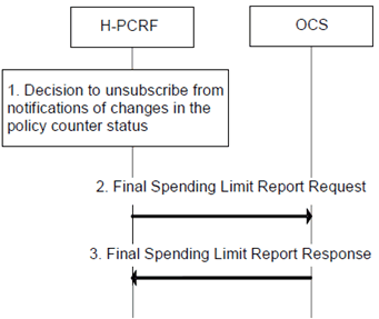
This clause describes the signalling flow for the H-PCRF to cancel the subscriptions to status changes for the policy counters available at the OCS.
Step 1.
The H-PCRF decides that notifications of policy counter status changes are no longer needed.
Step 2.
The H-PCRF sends a Final Spending Limit Report Request to the OCS to cancel the subscription to notifications of policy counter status changes from the OCS.
Step 3.
The OCS removes the H-PCRF's subscription to spending limit reporting and acknowledges the request by sending the Final Spending Limit Report Response to the H-PCRF.
7.9.4 Spending Limit Report p. 161
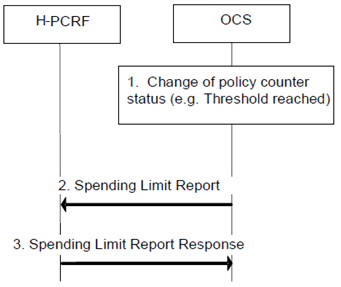
This clause describes the signalling flow for the OCS to notify the change of the status of the subscribed policy counters available at the OCS for that subscriber. Alternatively, the signalling flow can be used by the OCS to provide one or more pending statuses for a subscribed policy counter together with the time they have to be applied.
Step 1.
The OCS detects that the status of a policy counter(s) has changed and the PCRF subscribed to notifications of changes in the status of this policy counter. Alternatively, the OCS may detect that a policy counter status will change at a future point in time and decides to instruct the PCRF to apply one or more pending statuses for a requested policy counter.
Step 2.
The OCS sends the policy counter status and optionally pending policy counter statuses and their activation times, for each policy counter that has changed and for which the H-PCRF subscribed to spending limit reporting. Alternatively, the OCS sends one or more pending statuses for any of the subscribed policy counters together with the time they have to be applied.
Step 3.
The H-PCRF acknowledges the Spending Limit Report and takes that information into account as input for a policy decision.
7.9.5 Sy Session Termination |R15| p. 162
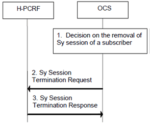
This clause describes the signalling flow for the OCS to terminate the Sy session of a subscriber. This feature is optional.
Step 1.
The OCS decides that the Sy session for a subscriber needs to be terminated.
Step 2.
The OCS sends the Sy Session Termination Request to H-PCRF to terminate the Sy session. The H-PCRF removes the Sy session context of the subscriber.
Step 3.
The H-PCRF acknowledges the termination of the Sy session of the subscriber by sending the Sy Session Termination Response.
7.10 Procedures over Np reference point |R13| p. 162
7.10.1 Report RAN user plane congestion information to PCRF p. 162
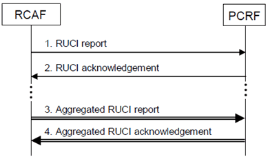
This clause describes the signalling flow for reporting RUCI (RAN User Plane Congestion Information) from the RCAF to the PCRF. Any RUCI changes shall be reported by RCAF unless reporting restrictions apply.
Two types of messages are used on Np for transfer of congestion information from RCAF to PCRF:
- Non-aggregated RUCI report messages, which are sent on a per UE per APN basis using DRA routing. The IMSI and the APN can be used to route messages.
- Aggregated RUCI report messages, which are sent between an RCAF and PCRF and contain congestion information for multiple UEs. A logical PCRF id is allocated for these aggregate messages which determine the destination of the message.
Step 1.
RCAF indicates congestion information for a given UE and APN in a RUCI report message. This message is routed by DRA to the appropriate PCRF based on IMSI and APN.
The RUCI report message includes the RUCI which is defined in clause 6.1.15.1.
Upon receiving the RUCI the PCRF stores the identity of the RCAF for the given UE if the RUCI indicates congestion. The PCRF makes a policy decision.
Step 2.
The PCRF allocates a logical PCRF id to identify the PCRF that is the Np destination for the given UE and APN for the RCAF when sending aggregate messages and reports the logical PCRF id in the RUCI acknowledgement.
The RCAF stores the logical PCRF id in the UE context for the given IMSI, APN combination.
Step 3.
Subsequent congestion information for the given UE can be sent as part of an Aggregated RUCI report message. Such a message can contain the congestion information for multiple UEs. These UEs can have different congestion levels associated with different eNB identifier or ECGI or SAI, which are indicated in the message. An aggregated RUCI report message is always destined to a single PCRF only and can be routed directly to that PCRF or via the DRA.
Step 4.
The Aggregated RUCI is acknowledged.
7.10.2 PCRF provided reporting restrictions p. 163
This clause describes the signalling flow for adding, updating or removing reporting restrictions for a given UE and APN. A pre-condition for this procedure is that the RCAF has already performed RUCI reporting for the given UE and APN. The PCRF stores the RCAF identity for the given UE when the RCAF performs RUCI reporting indicating congestion
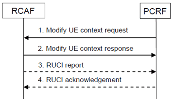
This procedure may be triggered by the initial RUCI report message for the given UE at an RCAF, or by other events, e.g. change in the subscription. The procedure is shown in Figure 7.10.2 below.
Step 1.
PCRF sends a Modify UE context request to the RCAF of the given UE and APN using the stored identity of the RCAF, specifying the new reporting restrictions or the removal of the reporting restrictions. The RCAF stores the new reporting restrictions or removes the reporting restrictions accordingly.
Step 2.
The RCAF sends a Modify UE context response back to the PCRF to notify the PCRF about the success of the change in the reporting restrictions.
Step 3.
In case the RCAF already had reporting restrictions for the UE and the APN which are changed in step 2, this may trigger RUCI reporting as specified in clause 7.10.1. This occurs in case of a change from disabled reporting to enabled reporting, or if some reporting restrictions are lifted. The RCAF uses the RUCI report message to report congestion information to the PCRF if it is allowed by the change in the reporting restrictions.
Step 4.
The RUCI is acknowledged.
7.10.3 UE mobility between RCAFs p. 164
This clause describes the handling mobility of a UE from one RCAF to a different RCAF. The PCRF applies the rules described in clause 6.1.15.3.
The process is shown in Figure 7.10.3 below for the case when the UE is affected by congestion at RCAF2 after the UE was earlier affected by congestion at RCAF1.
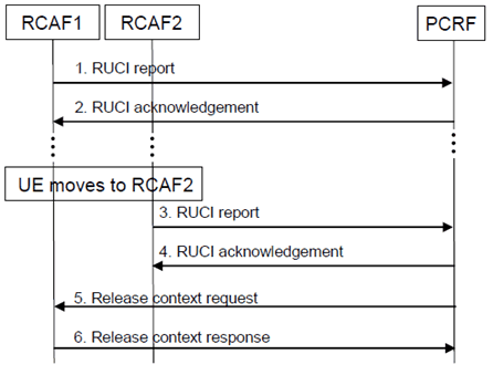
Figure 7.10.3: UE mobility from RCAF1 to RCAF2 in case UE is affected by congestion at RCAF2 after the UE was earlier affected by congestion at RCAF1
(⇒ copy of original 3GPP image)
(⇒ copy of original 3GPP image)
Step 1.
RCAF1 reports RAN user plane congestion information (RUCI). The PCRF stores the identity of the current RCAF1 for a given UE when it receives the congestion information over Np that is different from no congestion.
Step 2.
The RUCI is acknowledged.
Step 3.
The UE moves to RCAF2 where it is affected by congestion. RCAF2 reports RAN user plane congestion information (RUCI). The PCRF stores the identity of the current RCAF2 for the given UE when it receives the congestion information over Np that is different from no congestion.
Step 4.
The RUCI is acknowledged.
Step 5.
Using on the previously stored identity of the old RCAF, the PCRF sends a Release context request message to RCAF1.
Step 6.
RCAF1 acknowledges this by sending the Release context response message to the PCRF. The RCAF releases the context corresponding to the given UE and given APN, including any reporting restrictions. This also implies that the RCAF does not indicate to the PCRF that the congestion state is over. In case of multiple PCRFs being in simultaneous use for a given UE, a Release context request message from a PCRF applies to the given Np connection only identified by the APN. The RCAF can completely release all context information for a given UE when it has released the context for each Np connection of the given UE.
7.11 Procedures over Nt reference point |R13| p. 165
7.11.1 Negotiation for future background data transfer p. 165
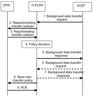
This procedure enables the negotiation between the SCEF and the H-PCRF about the time window and the related conditions for future background data transfer (as described in clause 6.1.16). The interaction between the SCEF and the H-PCRF is not related to an IP-CAN session and the H-PCRF associates the information provided by the SCEF to the policies belonging to the ASP and stored in the SPR.
Step 1.
Based on an AF request, the SCEF sends a Background data transfer request to the H-PCRF. The background data transfer request contains ASP identifier, the volume of data to be transferred per UE, the expected amount of UEs, the desired time window and optionally, network area information (e.g. list of cell ids, TAs/RAs).
Step 2.
The H-PCRF requests from the SPR all existing transfer policies.
Step 3.
The SPR provides all existing transfer policies and corresponding network area information to the H-PCRF.
Step 4.
The H-PCRF determines, based on information provided by the AF and other available information (see clause 6.1.16) one or more transfer policies. A transfer policy consists of a recommended time window for the background data transfer, a reference to a charging rate for this time window and optionally a maximum aggregated bitrate.
Step 5.
The H-PCRF sends a Background data transfer response to the SCEF with the possible transfer policies and a reference ID.
Step 6.-7.
If the SCEF receives more than one transfer policy, the AF selects one of them and send another Background data transfer request to inform the H-PCRF about the selected transfer policy. The H-PCRF sends a Background data transfer response to the SCEF to acknowledge the selection.
Step 8.
The H-PCRF stores the reference ID together with the new transfer policy and the corresponding network area information in the SPR.
Step 9.
The SPR sends an acknowledgement to the H-PCRF.
7.12 Procedures for management of PFDs |R14| p. 166
7.12.1 PFD Retrieval by the PCEF/TDF ("Pull mode") p. 166
This procedure enables the PCEF/TDF to retrieve PFDs for an Application Identifier from the PFDF when a PCC/ADC Rule with an Application Identifier is provisioned/activated and PFDs provisioned by the PFDF are not available at the PCEF/TDF.
In addition, this procedure enables the PCEF/TDF to retrieve PFDs from the PFDF when the caching timer for an Application Identifier elapses and a PCC/ADC Rule for this Application Identifier is still active.
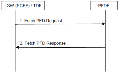
The PCEF/TDF may retrieve PFDs for one or more Application Identifiers in the same Request. All PFDs related to an Application Identifier is provided in the response from the PFDF. The signalling flow of PFD Retrieval is depicted in Figure 7.12.1-1 as below.
Step 1.
When one of the above mentioned conditions is met, PCEF/TDF shall fetch from the PFDF the PFDs for the Application Identifier(s) by sending Fetch PFD Request, in which the Application Identifier(s) is included.
Step 2.
The PFDF shall response with the list of Application Identifier and all associated PFDs in the Fetch PFD Response message. The PCEF/TDF shall bind the PFDs received from the PFDF to the respective Application Identifier.
7.12.2 Management of PFDs in the PCEF/TDF ("push mode") p. 167
This procedure enables the provisioning, modification or removal of PFDs associated with an application identifier in the PCEF/TDF via PFDF. Either the complete list of all PFDs of all application identifiers, the complete list of all PFDs of one or more application identifiers or a subset of PFDs for individual application identifiers may be managed.
Each PFD of an application identifier is associated with a PFD id in case a subset of the PFD(s) associated with an application identifier can be provisioned, updated or removed. In case always the full set of PFD(s) for an application identifier is managed in each transaction, PFD ids do not need to be provided.
The interaction between the PFDF and the PCEF/TDF is not related to an IP-CAN session.
The PFDF may decide to delay the distribution of PFDs to PCEFs/TDFs for some time to optimize the signalling load over the Gw/Gwn interface. If the PFDF received an Allowed Delay for a PFD, the PFDF shall distribute this PFD within the indicated time interval.
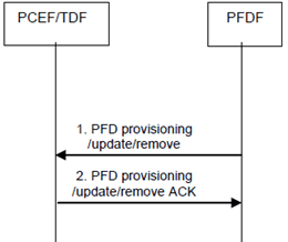
Figure 7.12.2-1: Provisioning/update/removal of PFDs in the PCEF/TDF
(⇒ copy of original 3GPP image)
(⇒ copy of original 3GPP image)
Step 1.
The PFDF may provision, update or remove one, multiple, or all PFDs associated with an application identifier. The PFDF may manage PFDs for more than one application identifier at the same time. Alternatively, the PFDF may provision or remove the list of all PFDs associated with all application identifiers.
Step 2.
The PCEF/TDF binds (for provision or update) or unbinds (for removal) the PFDs to the application identifier received from the PFDF. The provisioning of PFDs associates new PFDs to an application identifier. The PFDF may also provide a PFD id for each PFD provided. The update of PFDs modifies existing PFDs associated to an application identifier. Either all PFDs of an application identifier are replaced, or a subset of the PFDs are replaced, where each PFD is identified by a PFD id. Partial modification of a PDF is not supported. The removal of PFDs removes some or all existing PFDs associated to an application identifier. In the case of removal of a subset of the PFD(s), each PFD is identified by a PFD id. The PCEF/TDF acknowledges the reception of the PFDs to the PFDF.