Content for TS 23.203 Word version: 19.1.0
0…
4…
5…
6…
6.1.4…
6.1.7…
6.1.10…
6.1.17…
6.2…
6.2.2…
6.2.3…
6.3
6.4…
6.8…
7…
7.3…
7.4…
7.7…
7.7.3…
7.8…
A…
A.4…
D…
P…
P.4.2.4…
P.7…
P.7.5…
P.8
Q…
S…
S.7…
S.8.8
T…
7.7.3 Gateway Control and QoS Rules Request p. 155
7.7.3.1 General p. 155
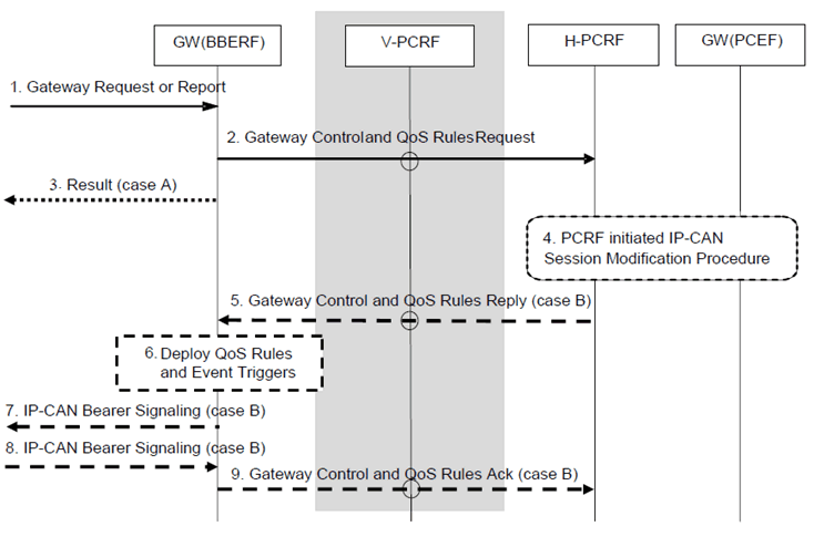
There are two cases considered for a Gateway Control and QoS Rules Request depending on the parameters the GW (BBERF) receives:
Case A:
In case the GW (BBERF) action does not depend on the subsequent IP-CAN session modification, the GW (BBERF) can acknowledge the request after interacting with the PCRF.
Case B:
The GW (BBERF) is requested to obtain QoS rules for a Gateway Control Session or to deliver IP-CAN-specific parameters or both.

This procedure concerns both roaming and non-roaming scenarios. In the roaming case when a Gateway Control Session is used, the V-PCRF should proxy the Gateway Control and QoS Rules Request between the BBERF in the VPLMN and the H-PCRF over S9 based on PDN-Id and roaming agreements.
In the non-roaming case (Figure 5.1-1) the V-PCRF is not involved.
Step 1.
The GW (BBERF) is requested to either report an event or obtain QoS rules or both for a Gateway Control Session.
Step 2.
The GW (BBERF) sends a Gateway Control and QoS Rules Request to the PCRF and includes the new IP-CAN bearer establishment modes if changed. The information sent by the GW (BBERF) to the PCRF includes: a request for resource authorization and/or a report corresponding to a deployed Event Trigger.
Step 3.
If the GW (BBERF) is only requested to report an event, the GW (BBERF) acknowledges the step 1 by sending a result to the entity that triggered this procedure.
Step 4.
The PCRF initiated IP-CAN Session Modification Procedure may occur as the result of the Gateway Control and QoS Rules Request procedure, either to forward an Event Report to the GW (PCEF) or to issue new or revised PCC Rules and Event Triggers, or both an Event Report and a PCC Rules and Event Triggers provision.
Step 5.
If the GW (BBERF) asked for new QoS rules or IP-CAN-specific parameters need to be delivered back to the GW (BBERF) or both, the PCRF sends a Gateway Control and QoS Rules Reply to the GW (BBERF). This interaction may include QoS Rules and Event Triggers. In case 2a a charging ID may be provided together with QoS rules.
If there are multiple BBFs associated with the IP-CAN session and the request in Step 2 is from a non-primary BBERF (see clause 6.2.1.5), only QoS rules corresponding to already activated PCC rules are included in the reply. If a request from a non-primary BBERF results in an authorization of a new QoS rule or to a modification of an existing QoS rules, the PCRF shall reject the request.
Step 6.
The QoS Rules and Event Triggers, if any, received by the GW (BBERF) are deployed. This will result in bearer binding being performed, according to the rules. This may result in the binding of additional SDFs or a change in the binding of previously bound SDFs. Subsequent events corresponding to the Event Triggers will cause an Event Report to be delivered to the PCRF by means of a Gateway Control and QoS Rules Request procedure.
Step 7.
The GW (BBERF) initiates the IP-CAN Bearer signalling if required for the QoS Rules and Event Triggers deployed in step 6.
Step 8.
The GW (BBERF) receives the response for the IP-CAN Bearer signalling.
Step 9.
If the step 5 contained new and/or modified QoS Rules, the result of the QoS rule activation is returned to the PCRF, indicating whether the resources requested have been successfully allocated.
7.7.3.2 Event reporting for PCEF in visited network and locally terminated Gxx interaction p. 157
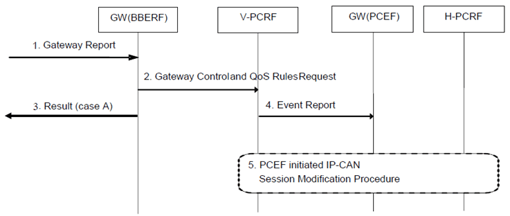
This procedure is only used for the event reporting for a PCEF in the visited network and when the Gxx interaction is locally terminated at the V-PCRF.

Figure 7.7.3-2: Event reporting for PCEF in visited network and locally terminated Gxx interaction
(⇒ copy of original 3GPP image)
(⇒ copy of original 3GPP image)
Step 1.
The GW (BBERF) is requested to report an event for a Gateway Control Session.
Step 2.
The GW (BBERF) sends a Gateway Control and QoS Rules Request to the V-PCRF and includes the new IP-CAN bearer establishment modes if changed. The information sent by the GW (BBERF) to the V-PCRF includes a report corresponding to a deployed Event Trigger.
Step 3.
Since the GW (BBERF) is only requested to report an event, the GW (BBERF) acknowledges the message received in step 1 by sending a result message to the entity that triggered this procedure.
Step 4.
The V-PCRF forwards the report corresponding to a deployed Event Trigger to the PCEF.
Step 5.
A PCEF initiated IP-CAN Session Modification Procedure may occur as the result of the received report, either to forward the report about the relevant deployed Event Trigger(s) to the H-PCRF or to request new or revised PCC Rules and Event Triggers, or both.
7.7.4 Gateway Control and QoS Rules Provision p. 158

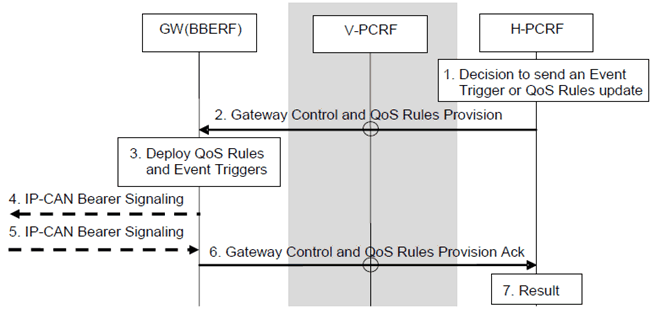
This procedure concerns both roaming and non-roaming scenarios. In the roaming case when a Gateway Control Session is used, the V-PCRF should proxy the Gateway Control and QoS Rules Provision between the BBERF in the VPLMN and the H-PCRF over S9 based on PDN-Id and roaming agreements.
In the non-roaming case (Figure 5.1-1) the V-PCRF is not involved.
Step 1.
The PCRF is requested to update the QoS Rules and Event triggers for a Gateway Control Session.
Step 2.
The PCRF sends a Gateway Control and QoS Rules Provision to the GW (BBERF). It will include QoS Rules and Event Triggers. In case 2a a charging ID may be provided together with QoS rules. If the service data flow is tunnelled at the BBERF, the information about the mobility protocol tunnelling encapsulation header may be included. It is also possible that this interaction includes an Event Report originating from the GW (PCEF) and relayed by the PCRF to the BBERF. This Event Report enables a GW (PCEF)-originating interaction to be sent by way of the PCC infrastructure to the BBERF in situations that communication is needed between the GW (PCEF) and the GW (BBERF) and no interface exists between the GWs.
Step 3.
The QoS Rules and Event Triggers received by the GW (BBERF) are deployed. This may result in bearer binding being performed, according to the rules. Subsequent events corresponding to the Event Triggers will cause an Event Report to be delivered to the PCRF by means of a Gateway Control and QoS Rules Request procedure.
Step 4.
The GW (BBERF) initiates the IP-CAN Bearer signalling if required for the QoS Rules and Event Triggers deployed in step 3.
Step 5.
The GW (BBERF) receives the response for the IP-CAN Bearer signalling.
Step 6.
The GW (BBERF) sends a Gateway Control and QoS Rules Provision Ack (Result) to the PCRF. The Result information element indicates whether the indicated QoS Rules could be implemented.
Step 7.
The PCRF has completed updating the session and can continue with the activity that prompted this procedure.
If there are multiple BBFs associated with the IP-CAN session (see clause 6.2.1.5), then the processing of the response is as follows depending on whether the BBERF is a primary BBERF or a non-primary BBERF:
- If a primary-BBERF reports failure to install a QoS rule in Step 4, the PCRF also removes the same QoS rule from the non-primary BBERF(s) if any. The PCRF also removes the corresponding PCC rule from the PCEF.
- If a non-primary BBERF reports failure to install a QoS rule, the PCRF updates the enforcement status of the QoS rule for that particular BBERF in its record but does not perform any further action.