Content for TS 23.203 Word version: 19.1.0
0…
4…
5…
6…
6.1.4…
6.1.7…
6.1.10…
6.1.17…
6.2…
6.2.2…
6.2.3…
6.3
6.4…
6.8…
7…
7.3…
7.4…
7.7…
7.7.3…
7.8…
A…
A.4…
D…
P…
P.4.2.4…
P.7…
P.7.5…
P.8
Q…
S…
S.7…
S.8.8
T…
5 Architecture model and reference points p. 29
5.1 Reference architecture p. 29
The PCC functionality is comprised by the functions of the Policy and Charging Enforcement Function (PCEF), the Bearer Binding and Event Reporting Function (BBERF), the Policy and Charging Rules Function (PCRF), the Application Function (AF), the Traffic Detection Function (TDF), the Traffic Steering Support Function (TSSF), the Online Charging System (OCS), the Offline Charging System (OFCS) and the Subscription Profile Repository (SPR) or the User Data Repository (UDR). UDR replaces SPR when the UDC architecture as defined in TS 23.335 is applied to store PCC related subscription data. In this deployment scenario Ud interface between PCRF and UDR is used to access subscription data in the UDR.
The PCRF can receive RAN User Plane Congestion Information from the RAN Congestion Awareness Function (RCAF).
The PCC architecture extends the architecture of an IP-CAN, where the Policy and Charging Enforcement Function is a functional entity in the Gateway node implementing the IP access to the PDN. The allocation of the Bearer Binding and Event Reporting Function is specific to each IP-CAN type and specified in the corresponding Annex.
The non-3GPP network relation to the PLMN is the same as defined in TS 23.402.
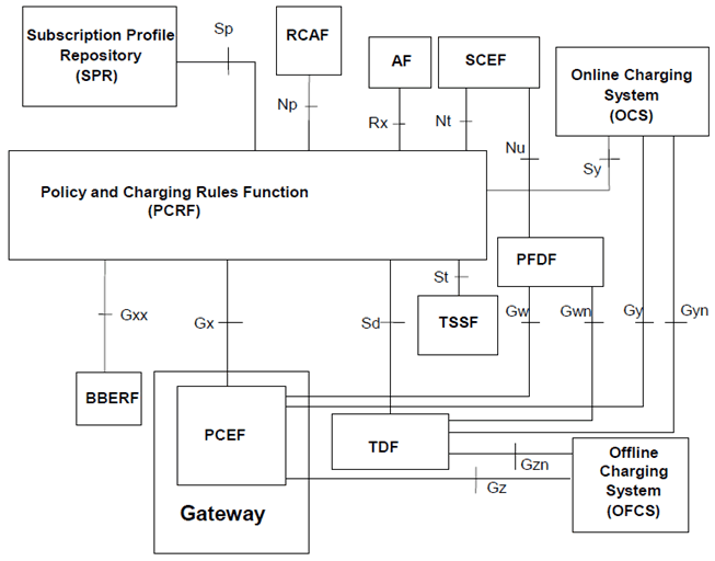
Figure 5.1-1: Overall PCC logical architecture (non-roaming) when SPR is used
(⇒ copy of original 3GPP image)
(⇒ copy of original 3GPP image)
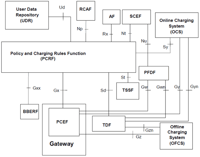
Figure 5.1-2: Overall PCC logical architecture (non-roaming) when UDR is used
(⇒ copy of original 3GPP image)
(⇒ copy of original 3GPP image)
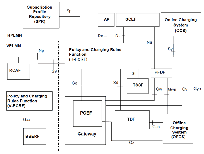
Figure 5.1-3: Overall PCC architecture (roaming with home routed access) when SPR is used
(⇒ copy of original 3GPP image)
(⇒ copy of original 3GPP image)
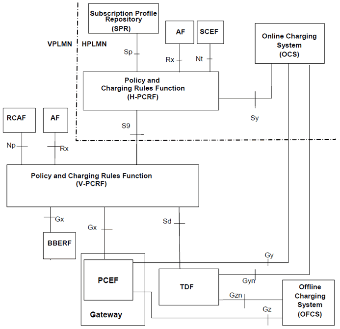
Figure 5.1-4: Overall PCC architecture for roaming with PCEF in visited network (local breakout) when SPR is used
(⇒ copy of original 3GPP image)
(⇒ copy of original 3GPP image)
5.2 Reference points p. 32
5.2.1 Rx reference point p. 32
The Rx reference point resides between the AF and the PCRF.
This reference point enables transport of application level session information from AF to PCRF. Such information includes, but is not limited to:
- IP filter information to identify the service data flow for policy control and/or differentiated charging;
-
Media/application bandwidth requirements for QoS control.
- In addition, for sponsored data connectivity:
- the sponsor's identification,
- optionally, a usage threshold and whether the PCRF reports these events to the AF,
- information identifying the application service provider and application (e.g. SDFs, application identifier, etc.).
- Re-try interval, which indicates when service delivery may be retried on Rx.
5.2.2 Gx reference point p. 32
The Gx reference point resides between the PCEF and the PCRF.
The Gx reference point enables the PCRF to have dynamic control over the PCC behaviour at a PCEF.
The Gx reference point enables the signalling of PCC decision, which governs the PCC behaviour and it supports the following functions:
- Establishment of Gx session (corresponding to an IP-CAN session) by the PCEF;
- Request for PCC decision from the PCEF to the PCRF;
- Provision of IP flow mobility routing information from PCEF to PCRF; this applies only when IP flow mobility as defined in TS 23.261 is supported;
- Provision of PCC decision from the PCRF to the PCEF;
- Reporting of the start and the stop of detected applications and transfer of service data flow descriptions and application instance identifiers for detected applications from the PCEF to the PCRF;
- Reporting of the accumulated usage of network resources on a per IP-CAN session basis from the PCEF to the PCRF;
- Delivery of IP-CAN session specific parameters from the PCEF to the PCRF or, if Gxx is deployed, from the PCRF to the PCEF per corresponding request;
- Negotiation of IP-CAN bearer establishment mode (UE-only or UE/NW);
- Termination of Gx session (corresponding to an IP-CAN session) by the PCEF or the PCRF.
5.2.3 Reference points to subscriber databases p. 33
5.2.3.1 Sp reference point |R10| p. 33
The Sp reference point lies between the SPR and the PCRF.
The Sp reference point allows the PCRF to request subscription information related to the IP-CAN transport level policies from the SPR based on a subscriber ID, a PDN identifier and possible further IP-CAN session attributes, see Annex A and Annex D. For example, the subscriber ID can be IMSI. The reference point allows the SPR to notify the PCRF when the subscription information has been changed if the PCRF has requested such notifications. The SPR shall stop sending the updated subscription information when a cancellation notification request has been received from the PCRF.
5.2.3.2 Ud reference point |R10| p. 33
5.2.4 Gy reference point p. 33
The Gy reference point resides between the OCS and the PCEF.
The Gy reference point allows online credit control for service data flow based charging. The functionalities required across the Gy reference point are defined in TS 32.251 and is based on RFC 4006.
5.2.5 Gz reference point p. 33
The Gz reference point resides between the PCEF and the OFCS.
The Gz reference point enables transport of service data flow based offline charging information.
The Gz interface is specified in TS 32.240.
5.2.6 S9 reference point |R8| p. 33
The S9 reference point resides between a PCRF in the HPLMN (H-PCRF) and a PCRF in the VPLMN (V-PCRF).
For roaming with a visited access (PCEF and, if applicable, BBERF in the visited network), the S9 reference point enables the H-PCRF to (via the V-PCRF):
- have dynamic PCC control, including the PCEF and, if applicable, BBERF and, if applicable, TDF, in the VPLMN;
- deliver or receive IP-CAN-specific parameters from both the PCEF and, if applicable, BBERF, in the VPLMN;
- serve Rx authorizations and event subscriptions from an AF in the VPLMN;
- receive application identifier, service data flow descriptions, if available, application instance identifiers, if available and application detection start/stop event triggers report.
5.2.7 Gxx reference point |R8| p. 34
The Gxx reference point resides between the PCRF and the BBERF. This reference point corresponds to the Gxa and Gxc, as defined in TS 23.402 and further detailed in the annexes.
The Gxx reference point enables a PCRF to have dynamic control over the BBERF behaviour.
The Gxx reference point enables the signalling of QoS control decisions and it supports the following functions:
- Establishment of Gxx session by BBERF;
- Termination of Gxx session by BBERF or PCRF;
- Establishment of Gateway Control Session by the BBERF;
- Termination of Gateway Control Session by the BBERF or PCRF;
- Request for QoS decision from BBERF to PCRF;
- Provision of QoS decision from PCRF to BBERF;
- Delivery of IP-CAN-specific parameters from PCRF to BBERF or from BBERF to PCRF;
- Negotiation of IP-CAN bearer establishment mode (UE-only and UE/NW).
5.2.8 Sd reference point |R11| p. 34
The Sd reference point resides between the PCRF and the TDF.
The Sd reference point enables a PCRF to have dynamic control over the application detection and control behaviour at a TDF.
The Sd reference point enables the signalling of ADC decision, which governs the ADC behaviour and it supports the following functions:
- Establishment of Sd session between the PCRF and the TDF;
- Termination of Sd session between the PCRF and the TDF;
- Provision of ADC decision from the PCRF for the purpose of application's traffic detection, enforcement and charging at the TDF;
- Request for ADC decision from the TDF to the PCRF;
- Reporting of the start and the stop of a detected applications and transfer of service data flow descriptions and application instance identifiers for detected applications from the TDF to the PCRF;
- Reporting of the accumulated usage of network resources on a per TDF session basis from the TDF to the PCRF;
- Request and delivery of IP-CAN session specific parameters between the PCRF and the TDF.
- Provision of ADC Rules from the PCRF for the purpose of application's traffic detection and traffic steering control.
5.2.9 Sy reference point |R11| p. 35
The Sy reference point resides between the PCRF and the OCS.
The Sy reference point enables transfer of policy counter status information relating to subscriber spending from OCS to PCRF and supports the following functions:
- Request for reporting of policy counter status information from PCRF to OCS and subscribe to or unsubscribe from spending limit reports (i.e. notifications of policy counter status changes).
- Report of policy counter status information upon a PCRF request from OCS to PCRF.
- Notification of spending limit reports from OCS to PCRF.
- Cancellation of spending limit reporting from PCRF to OCS.
5.2.10 Gyn reference point |R12| p. 35
The Gyn reference point resides between the OCS and the TDF.
The Gyn reference point allows online credit control for charging in case of ADC rules based charging in TDF. The functionalities required across the Gyn reference point are defined in TS 32.251 and is based on RFC 4006.
5.2.11 Gzn reference point |R12| p. 35
The Gzn reference point resides between the TDF and the OFCS.
The Gzn reference point enables transport of offline charging information in case of ADC rule based charging in TDF.
The Gzn interface is specified in TS 32.240.
5.2.12 Np reference point |R13| p. 35
The Np reference point resides between the RCAF and the PCRF.
The Np reference point enables transport of RAN User Plane Congestion Information (RUCI) sent from the RCAF to the PCRF for all or selected subscribers, depending on the operator's congestion mitigation policy.
The Np reference point supports the following functions:
- Reporting of RUCI from the RCAF to the PCRF.
- Sending, updating and removal of the reporting restrictions from the PCRF to the RCAF as defined in clause 6.1.15.2.
5.2.13 Nt reference point |R13| p. 35
The Nt reference point enables the negotiation between the SCEF and the PCRF about the recommended time window(s) and the related conditions for future background data transfer. The SCEF is triggered by an SCS/AS (as described in TS 23.682) which requests for this negotiation and provides necessary information to the SCEF. The SCEF will forward the information received from the SCS/AS to the PCRF as well as the information received from the PCRF to the SCS/AS.
Whenever the SCEF contacts the PCRF, the PCRF shall use the information provided by the SCS/AS via the SCEF to determine the policies belonging to the application service provider (ASP).
5.2.14 St reference point |R13| p. 36
The St reference point resides between the TSSF and the PCRF.
The St reference point enables the PCRF to provide traffic steering control information to the TSSF.
The St reference point supports the following functions:
- Provision, modification and removal of traffic steering control information from PCRF to the TSSF.
5.2.15 Nu reference point |R14| p. 36
The Nu reference point resides between the SCEF and the PFDF and enables the 3rd party service provider to manage PFDs in the PFDF as specified in TS 23.682.
5.2.16 Gw reference point |R14| p. 36
The Gw reference point resides between the PFDF and the PCEF.
The Gw reference point enables transport of PFDs from the PFDF to the PCEF for a particular Application Identifier or for a set of Application Identifiers.
The Gw reference point supports the following functions:
- Creation, updating and removal of individual or the whole set of PFDs from the PFDF to the PCEF.
- Confirmation of creation, updating and removel of PFDs from the PCEF to the PFDF.
5.2.17 Gwn reference point |R14| p. 36
The Gwn reference point resides between the PFDF and the TDF.
The Gwn reference point enables transport of PFDs from the PFDF to the TDF for a particular Application Identifier or for a set of Application Identifiers.
The Gwn reference point supports the following functions:
- Creation, updating and removal of individual or the whole set of PFDs from the PFDF to the TDF.
- Confirmation of creation, updating and removel of PFDs from the PCEF to the TDF.
![]()
![]()
![]()