Content for TS 23.002 Word version: 18.0.0
5.11 Configuration of Policy Control and Charging entities
5.12 Configuration of CSFB(CS Fallback)
5.13 Configuration of Single Radio Voice Call Continuity (SRVCC)
5.14 Configuration of Security
5.15 Configuration of Lawful Intercept related entities
5.16 Configuration of Charging related entities
...
...
5.11 Configuration of Policy Control and Charging entities |R8| p. 67
The PCC functionality is comprised by the functions of the Policy and Charging Enforcement Function (PCEF), the Bearer Binding and Event Reporting Function (BBERF), the Policy and Charging Rules Function (PCRF), the Application Function (AF), the Online Charging System (OCS), the Offline Charging System (OFCS), the Traffic Detection Function (TDF), the Traffic Steering Support Function (TSSF) and the Subscription Profile Repository (SPR) or the User Data Repository (UDR). Figures 5.11-1 through to 5.11-4 describe the non-roaming and roaming architecture for PCC.
The PCRF can receive RAN User Plane Congestion Information from the RAN Congestion Awareness Function (RCAF).
The PCC architecture extends the architecture of an IP-CAN, where the Policy and Charging Enforcement Function is a functional entity in the Gateway node implementing the IP access to the PDN. The allocation of the Bearer Binding and Event Reporting Function is specific to each IP-CAN type and specified in the TS 23.203.
PCC function makes it possible to apply policy and charging control to any kind of 3GPP IP CAN and any non-3GPP accesses connected via EPC complying with TS 23.402. Applicability of PCC to other IP CAN is not restricted; however, it shall be possible for the PCC architecture to base decisions upon the type of IP CAN used (e.g. GPRS, I-WLAN, etc.). Support for policy control and charging when local breakout and roaming are applied as specified in TS 23.401 and TS 23.402 is supported.
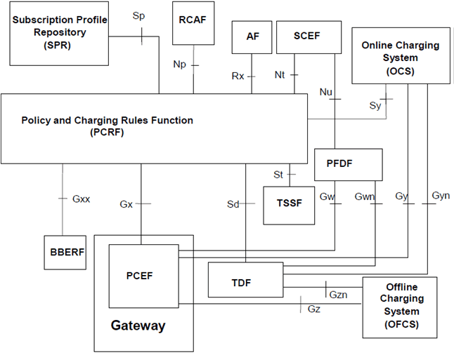
Figure 5.11-1: Overall PCC logical architecture (non-roaming) when SPR is used
(⇒ copy of original 3GPP image)
(⇒ copy of original 3GPP image)
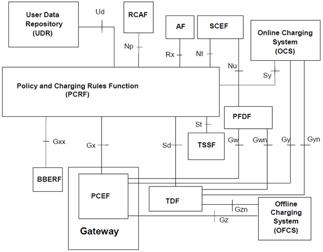
Figure 5.11-2: Overall PCC logical architecture (non-roaming) when UDR is used
(⇒ copy of original 3GPP image)
(⇒ copy of original 3GPP image)
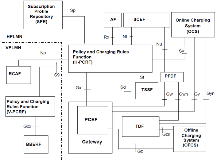
Figure 5.11-3: Overall PCC architecture (roaming with home routed access) when SPR is used
(⇒ copy of original 3GPP image)
(⇒ copy of original 3GPP image)
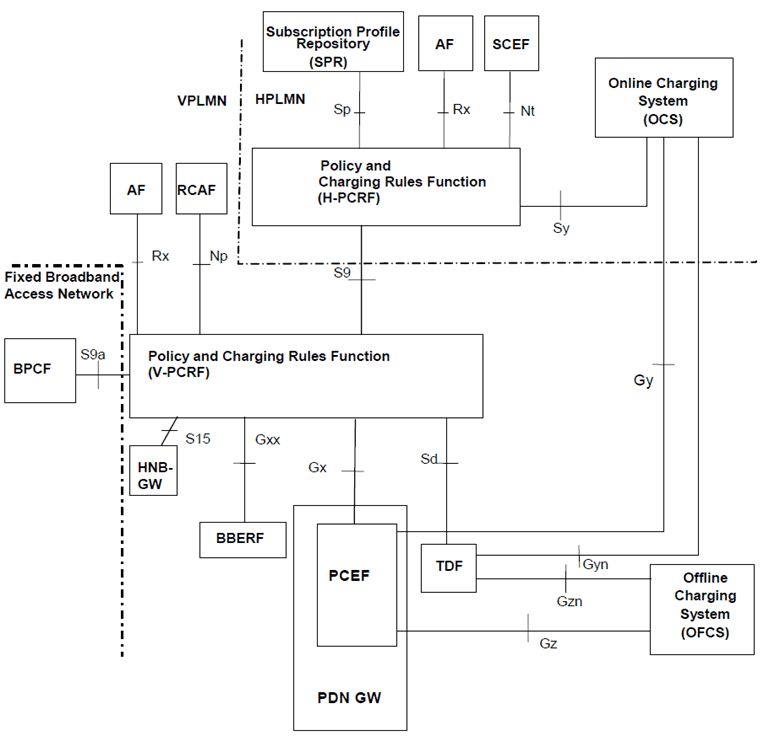
Figure 5.11-4: Overall PCC architecture for roaming with PCEF in visited network (local breakout) when SPR is used
(⇒ copy of original 3GPP image)
(⇒ copy of original 3GPP image)
5.12 Configuration of CSFB(CS Fallback) |R8| p. 70
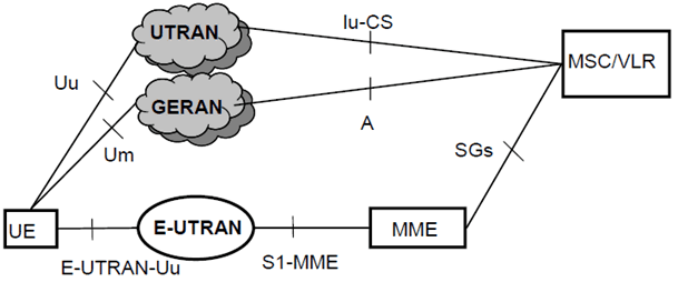
The CS fallback in EPS enables the provisioning of voice and other CS-domain services (e.g. CS UDI video/ SMS/ LCS/ USSD) by reuse of CS infrastructure when the UE is served by E-UTRAN. This function is only available in case E-UTRAN coverage is overlapped by either GERAN coverage or UTRAN coverage.
The configurations of the CSFB entities are represented in Figure 5.12.
5.13 Configuration of Single Radio Voice Call Continuity (SRVCC) |R8| p. 71
5.13.1 E-UTRAN/UTRAN (HSPA) to UTRAN or GERAN SRVCC architecture |R11| p. 71
Single Radio Voice Call Continuity (PS to CS) refers to continuity between IMS over PS access and CS calls that are anchored in IMS when the UE is capable of transmitting/receiving on only one of those access networks at a given time. PS to CS SRVCC is specified in TS 23.216. The following Figure 5.13, Figure 5.13a and Figure 5.13b show the entities involved in PS to CS SRVCC.
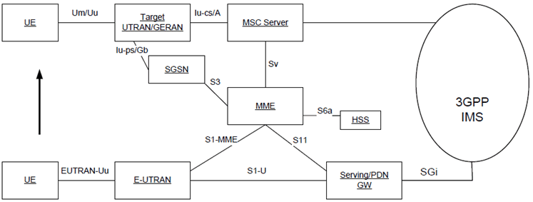
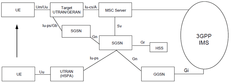
Figure 5.13a: SRVCC architecture for UTRAN (HSPA) to 3GPP UTRAN/GERAN with Gn based SGSN
(⇒ copy of original 3GPP image)
(⇒ copy of original 3GPP image)
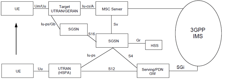
Figure 5.13b: PS to CS SRVCC architecture for UTRAN (HSPA) to 3GPP UTRAN/GERAN with S4 based SGSN
(⇒ copy of original 3GPP image)
(⇒ copy of original 3GPP image)
5.13.2 UTRAN/GERAN to E-UTRAN or UTRAN (HSPA) SRVCC architecture |R11| p. 72
CS to PS Single Radio Voice Call Continuity refers to continuity between a CS call and IMS call over PS access that are anchored in IMS when the UE is capable of transmitting/receiving on only one of those access networks at a given time. CS to PS SRVCC is specified in TS 23.216. The following Figure 5.13c, Figure 5.13d and Figure 5.13e show the entities involved in CS to PS SRVCC.
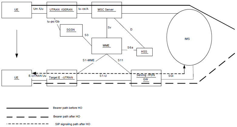
Figure 5.13c: CS to PS SRVCC architecture for UTRAN/GERAN to E-UTRAN
(⇒ copy of original 3GPP image)
(⇒ copy of original 3GPP image)
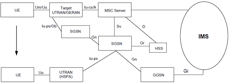
Figure 5.13d: CS to PS SRVCC architecture for UTRAN/GERAN to UTRAN (HSPA) with Gn based SGSN
(⇒ copy of original 3GPP image)
(⇒ copy of original 3GPP image)
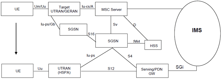
Figure 5.13e: CS to PS SRVCC architecture for UTRAN/GERAN to UTRAN (HSPA) with S4 based SGSN
(⇒ copy of original 3GPP image)
(⇒ copy of original 3GPP image)
5.14 Configuration of Security |R8| p. 74
The reference architecture model, the reference points and the functional entities to support and provide security related functions to the users, devices and network entities when in the UTRAN access as well as using IMS are described in TS 33.1xx series and TS 33.2xx series.
The reference architecture model, the reference points and the functional entities to support security functions to the users, devices and network entities when in the EPC are described in TS 33.401 for 3GPP access and in TS 33.402 for non-3GPP accesses.
5.15 Configuration of Lawful Intercept related entities |R8| p. 74
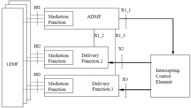
The general configuration for Lawful Interception is shown in Figure 5.15. The definition of the LI functional entities and interfaces is provided in TS 33.107.
The reference configuration is only a logical representation of the entities involved in lawful interception and does not mandate separate physical entities. There is one Administration Function (ADMF) in the network. Every physical Intercepting Control Element (ICE) is linked by its own X1_1-interface to the ADMF. Consequently, every single ICE performs interception (activation, deactivation, interrogation as well as invocation) independently from other ICEs.
5.16 Configuration of Charging related entities |R8| p. 75
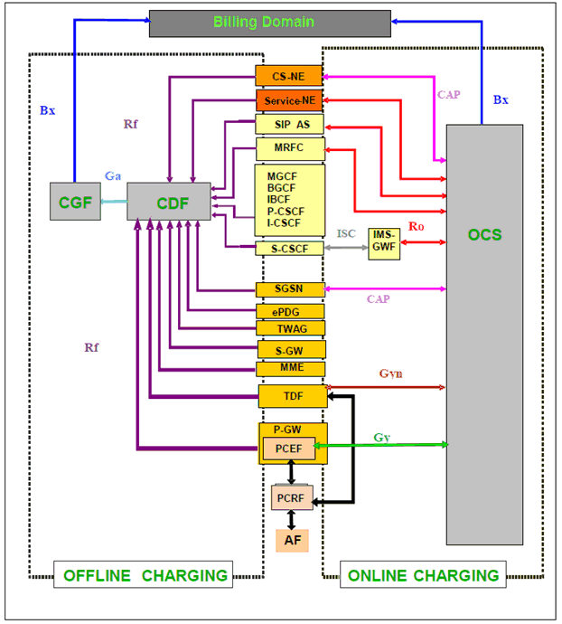
The general configuration for common charging architecture for 3GPP defined entities is shown in Figure 5.16 as defined in TS 32.240. This common charging architecture provides a logical view and the actual domain / service / subsystem specific charging architecture depends on the domain / service / subsystem in question. The physical mapping of the common logical architecture onto each domain, subsystem or service is described in the respective charging specifications, i.e. the TSs 32.25x, 32.26x and 32.27x number range.
3GPP networks provide functions that implement offline and/or online charging mechanisms on the bearer (e.g. EPC), subsystem (e.g. IMS) and service (e.g. MMS) levels. In order to support these charging mechanisms, the network performs real-time monitoring of resource usage on the above three levels in order to detect the relevant chargeable events.
In offline charging, the resource usage is reported from the network to the Billing Domain after the resource usage has occurred. In online charging, a subscriber account, located in an Online Charging System, is queried prior to granting permission to use the requested network resource(s).
Offline and online charging may be performed simultaneously and independently for the same chargeable event.
