Content for TR 38.877 Word version: 18.1.0
5.3.4 MIMO EM simulation results p. 27
To enhance the capacity and reliability of data transmission the BSs utilize MIMO of antenna arrays. Therefore, the antenna array designs need to ensure key metrics (such as isolation between antenna elements and diversity performance parameters) achievable in order to deliver expected MIMO performances. The following simulation results demonstrate the capability of a dual-band antenna array design to achieve acceptable performance metrics required for the MIMO.
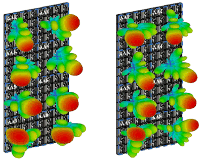
Uniform phased antenna arrays in multiple panels spanning beams in two dimensions (2D) are employed at BSs, to serve multiple users within the same time-frequency resource via spatial beamforming across the azimuth and elevation domains. Figure 5.3.4-1 shows the example of 2D multibeam scanning of an 8-panel massive MIMO antenna array system of in 3D view at 26 GHz and 38 GHz, which has been designed by considering antenna element separation of 0.5λ at higher limit. When various phased antenna arrays are employed in multiple panels in a small physical size, the mutual coupling between them can greatly affect the performance. The isolation between panels' adjacent antenna elements and correlation between the radiated beams needs to be ensured. The performance metrics are isolation (between antenna elements) and diversity performance parameters e.g. envelope correlation coefficient (ECC). The ECC is commonly used to measure amount of radiated beams correlation. The ECC values are calculated using radiated far-field equation in [23]. For good diversity action the ECC should be low.

Figure 5.3.4-1: Example of 2D multibeam scanning of an 8-panel MIMO antenna array system in 3D view: 26 GHz (left), 38 GHz (right)
(⇒ copy of original 3GPP image)
(⇒ copy of original 3GPP image)
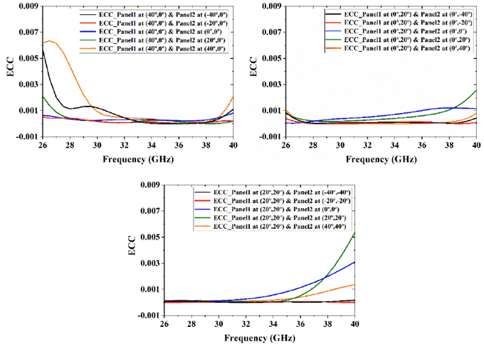
MIMO diversity performance of massive MIMO antenna system has been evaluated for three different cases by considering one panel steering the beam at different angles with respect to the other panels' main beam in a fixed direction.
Case 1:
When Panel 1 (AA1) radiates the field in the azimuth plane at (40°,0°) and Panel 2 (AA2) steers the beam at different angles i.e. -40°, -20°, 0°, 20°, and 40° in the azimuth plane.
Case 2:
When Panel 1 (AA1) radiates the field in the elevation plane at (0°, 20°) and Panel 3 (AA3) steers the beam at different angles i.e. -40°, -20°, 0°, 20°, and 40° in the elevation plane.
Case 3:
When Panel 1 (AA1) radiates field at (20°, 20°) and Panel 4 (AA4) steers beam at different angles i.e. (-40°, -40°), (-20°, -20°), (0°, 0°), (20°, 20°), and (40°, 40°).

Figure 5.3.4-2: Diversity performance: when beam steered in azimuth plane, when beam steered in elevation plane, when beam steered diagonally
(⇒ copy of original 3GPP image)
(⇒ copy of original 3GPP image)
BSs implemented with MIMO antenna systems can serve multiple users via spatial beamforming across the azimuth and elevation domains with good diversity performance over multiple frequency bands.