Content for TR 38.877 Word version: 18.1.0
5.2.3 Phase shifter p. 20
Analog phase shifters in mmWave BS are used to control the phase of signals in order to steer the beam. In some architectures, attenuators or variable-gain amplifiers are also placed along with the phase shifter to control the gain of beamformed signals to achieve desirable beamforming performance.
Considering phase shifter designs which are wideband it would prove difficult to apply different phase shifts to different bands. Hence it is not possible to independently steer beams to different directions in the different bands, and it may even not be feasible to steer the beams in the same directions for to 2 separate bands if the bands are sufficiently far apart in frequency that the beamforming weights would need to be different for each band.
If variable true time delay based phase shifters, which add delay to time-domain signals to create phase shift such as tapped delay line phase shifter, are used, then it may be possible to steer the beams toward the same direction for two different bands. This is because the frequency-dependent linear phase response of the true time delay phase shifter can create different phase shifts at different frequencies. However, true time delay phase shifts are challenging to implement due to the required size to delivered acceptable phase shift performance (e.g, phase shift resolution), while incurring high insertion loss.
Phase shifters with a frequency-flat phase response, such as vector modulated phase shifters may have cheaper implementational cost and be more feasible to integrated into commercial BFICs. However, since only one phase shift value can be controlled at a time instant, it may not be feasible to steer the beams in the same direction for two different bands if the bands are sufficiently far apart in frequency that the beamforming weights need to be different for each band.
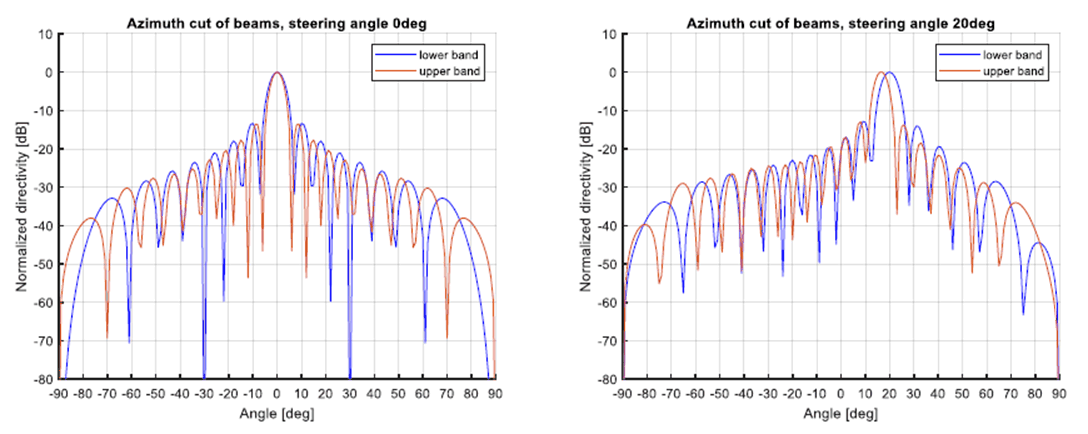
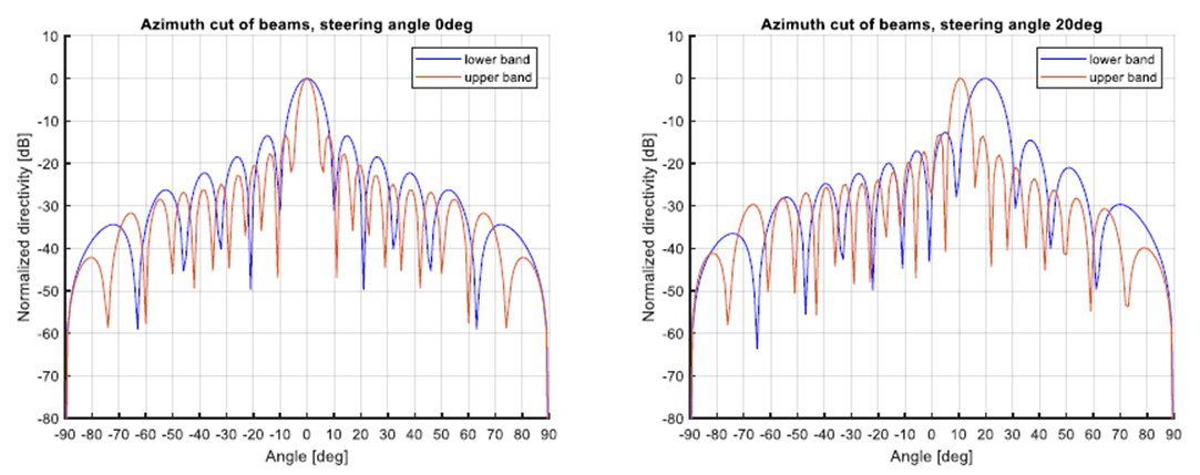
Examples of beam steering results when wide-band frequency-flat phase response phase shifters and wideband phased array are used in a multiband transmitter are shown below. The phase shifters only control the beam weights of the lower frequency band. Two steering angles are considered, i.e. 0 and 20 degrees. Figure 5.2.3-1 illustrates the beam patterns when the element separation for lower band and upper band is 0.5λ and 0.6λ, respectively, which corresponds to the case of, for example, the combination n258+n261. Figure 5.2.3-2 presents the case when the operating bands are further apart, i.e. the element separation for lower band and upper band is 0.35λ and 0.65λ, respectively, which can be the case of combinations across different frequency groups. As can be seen, except when UEs of different bands are at the boresight of the array, otherwise the transmitter cannot steer the beam to multiple UEs independently. Even if different-band UEs are located at same direction (but not boresight), the beam for upper-band UEs is not pointed to its desired direction and a larger frequency separation of the bands results in bigger error of the steering angle.

Figure 5.2.3-1: Beam pattern of different band signals when using wideband phase shifter and antenna array. Phase shifters apply beam weights for the lower band. Array separation for lower band 0.5λ, and upper band 0.6 λ: (Left) 0-degree steering angle; (Right) 20-degree steering angle
(⇒ copy of original 3GPP image)
(⇒ copy of original 3GPP image)

Figure 5.2.3-2: Beam pattern of different band signals when using wideband phase shifter and antenna array. Phase shifters apply beam weights for the lower band. Array separation for lower band 0.35λ, and upper band 0.65λ: (Left) 0-degree steering angle; (Right) 20-degree steering angle.
(⇒ copy of original 3GPP image)
(⇒ copy of original 3GPP image)
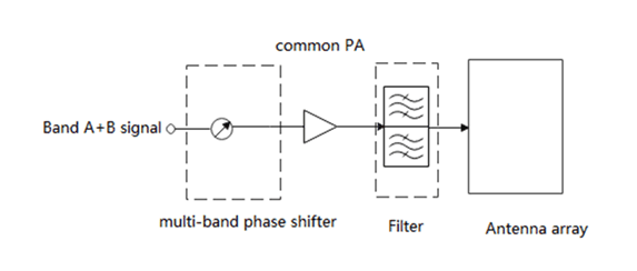
Thus, it is not clear such a wide band phase shifter as shown in Figure 5.2.3-3 would be of use. Within the time frame of this SI it seems commercially available multi-band frequency selective phase shifters that can apply a different phase shift per band are unlikely to be available. However, any specification should not preclude a potential future architecture based on frequency dependent phase shifters. If and when frequency dependent phase shifters become viable, it is possible that RAN4 requirements created in Rel-18 would need re-visiting.

Figure 5.2.3-3: Example of multi-band phase shifter prior to a multi-band PA
(⇒ copy of original 3GPP image)
(⇒ copy of original 3GPP image)
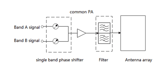
In order to apply independent phase shift and hence independent steering to each band, phase shifters need to be applied differently to each band. Using technology available today it may be possible to use multiple single band phase shifters to provide the beam steering to each band independently whilst feeding into a multi-band PA shown in Figure 5.2.3-4, although this may have some performance penalty.
Note that Figure 5.2.3-3 and Figure 5.2.3-4 show example architectures for a multi-band BS. Depending on the implementation, filter may or may not be placed after the multi-band PAs.

Figure 5.2.3-4: Example of single band phase shifter prior to a multi-band PA to steer each band separately
(⇒ copy of original 3GPP image)
(⇒ copy of original 3GPP image)