Content for TR 38.877 Word version: 18.1.0
5.3.3 Interleaved array structures p. 25
If the required multi-band antenna bandwidth is too great to be handled by a single antenna array (for the required steering range) it is also possible to use interleaved array structures such as stacked patches. Using stacked patches allows the different bands to feed different elements which are tuned for the specific band. This resolves some of the physical restrictions on the element size. However, if the arrays are stacked then restrictions still exist on the element separation in the array.
Stacked patches can be designed with either a single dual band input or with separate input ports. As the bands are separated (for example 26GHz and 40GHz), it is possible to implement a diplexer to separate the bands for each of the antenna arrays, if necessary.

Figure 5.3.3-1: Multi-band PA with stacked single band arrays (single and dual input ports)
(⇒ copy of original 3GPP image)
(⇒ copy of original 3GPP image)
A number of papers have been identified [19], [20], [21], and [22] which have demonstrated the feasibility of operational stacked patch antennas in the range 26 to 40 GHz
Dual band performance can be achieved by using multiple patches stacked on top of each other. For example, in [20] a simple stack with a high band patch and a low band patch with a single input port was shown. Using these patches, a 2x2 array was demonstrated with acceptable levels of input match, boresight gain isolation and scanning angle. Although of course such small arrays are more suitable for a handset than a BS.
In [22] a larger 8x4 array was demonstrated along with separate single band beamformers. While this is still small for BS purposes, it demonstrates the scalability of such structures and that larger BS-size arrays may be technically feasible to implement.
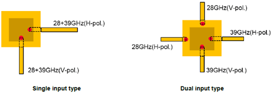
In the above configuration, there are two types of feed line such as single input and dual input. The following analysis shows the difference between their performance. The 28+39 GHz (n257/n261, n260) combination was analysed, and Figure 5.3.3-2 shows their structures. Both type support dual polarization. Upper patch is for Hi-band (n260) and lower patch is for Lo-band (n257/n261).

Figure 5.3.3-2: Dual polarized stacked patch antenna element for 28+39GHz combination
(⇒ copy of original 3GPP image)
(⇒ copy of original 3GPP image)
The following simulation result shows antenna gain of both stacked patch antenna elements.

Figure 5.3.3-3: Performance of multi-band stacked patch antenna element for 28+39GHz combination
(⇒ copy of original 3GPP image)
(⇒ copy of original 3GPP image)
| Antenna element gain [dBi] | ||||
|---|---|---|---|---|
| 26.5GHz | 29.5GHz | 37.0GHz | 40.0GHz | |
| Single input type | 4.99 | 5.65 | 5.07 | 4.67 |
| Dual input type | 4.47 | 5.37 | 4.42 | 4.26 |
From antenna performance perspective, the difference between single input and dual input of stacked patch multi-band antenna is small, and both types could achieve 4 to 5dBi element gain including frequency roll-off. Considering that 4 to 5dBi is generally set as the antenna element gain in a link budget for mmWave communication equipment, performance impact of both stacked patch multi-band antennas is small. In addition, it is possible to expand the support frequency range by increasing thickness of the antenna as needed.
From the above discussions for different antenna array structures, either a multi-band antenna array (broadband or with multi-resonances) or separate antenna arrays with lower percentage bandwidth can be used in FR2 multiband RIB/BS. In comparison to separate antenna arrays, a consolidated multi-band design is more compact and reduces costs, but trades performance aspects that can be optimized for in separate designs. On the other hand, having separate designs enables dedicated optimizations, yielding better performance. However, this comes at the cost of a significantly larger circuit area being used for two designs and additional integration losses from lines and transitions.