Content for TS 33.102 Word version: 18.0.0
6.6 Access link data confidentiality
6.6.1 General
6.6.2 Layer of ciphering
6.6.3 Ciphering method
6.6.4 Input parameters to the cipher algorithm
6.6.5 Cipher key selection
6.6.6 UEA identification
...
...
6.6 Access link data confidentiality p. 39
6.6.1 General p. 39
User data and some signalling information elements are considered sensitive and should be confidentiality protected. To ensure identity confidentiality (see clause 6.1), the temporary user identity (P-)TMSI should be transferred in a protected mode at allocation time and at other times when the signalling procedures permit it.
These needs for a protected mode of transmission are fulfilled by a confidentiality function which is applied on dedicated channels between the ME and the RNC.
6.6.2 Layer of ciphering p. 39
The ciphering function is performed either in the RLC sub-layer or in the MAC sub-layer, according to the following rules:
- If a radio bearer is using a non-transparent RLC mode (AM or UM), ciphering is performed in the RLC sub-layer.
- If a radio bearer is using the transparent RLC mode, ciphering is performed in the MAC sub-layer (MAC-d entity).
6.6.3 Ciphering method p. 39
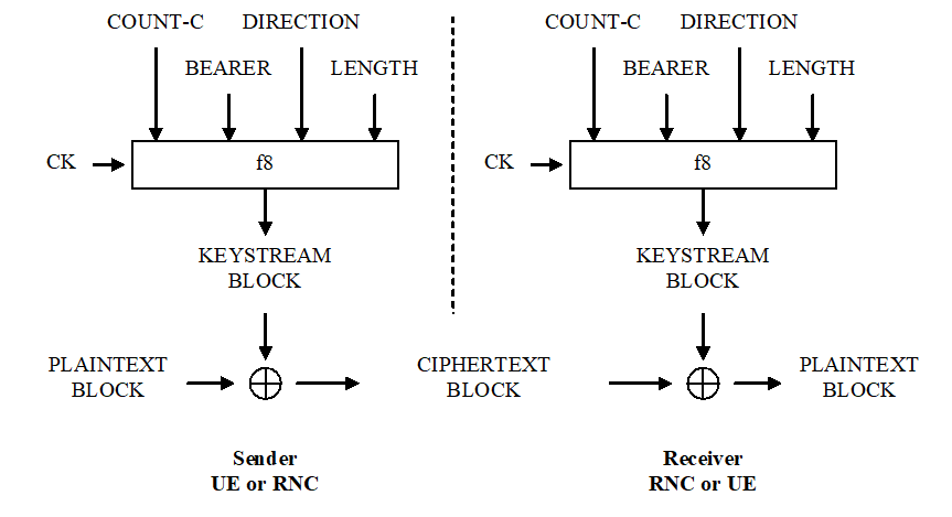
Figure 16b illustrates the use of the ciphering algorithm f8 to encrypt plaintext by applying a keystream using a bit per bit binary addition of the plaintext and the keystream. The plaintext may be recovered by generating the same keystream using the same input parameters and applying a bit per bit binary addition with the ciphertext.

Figure 16b: Ciphering of user and signalling data transmitted over the radio access link
(⇒ copy of original 3GPP image)
(⇒ copy of original 3GPP image)
The input parameters to the algorithm are the cipher key CK, a time dependent input COUNT-C, the bearer identity BEARER, the direction of transmission DIRECTION and the length of the keystream required LENGTH. Based on these input parameters the algorithm generates the output keystream block KEYSTREAM which is used to encrypt the input plaintext block PLAINTEXT to produce the output ciphertext block CIPHERTEXT.
The input parameter LENGTH shall affect only the length of the KEYSTREAM BLOCK, not the actual bits in it.
6.6.4 Input parameters to the cipher algorithm p. 40
6.6.4.1 COUNT-C p. 40
The ciphering sequence number COUNT-C is 32 bits long.
There is one COUNT-C value per up-link radio bearer and one COUNT-C value per down-link radio bearer using RLC AM or RLC UM. For all transparent mode RLC radio bearers of the same CN domain COUNT-C is the same, and COUNT-C is also the same for uplink and downlink.
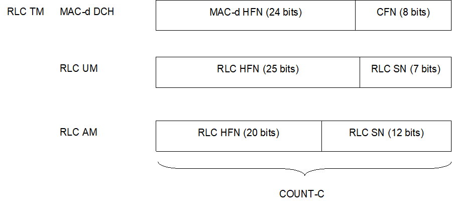
COUNT-C is composed of two parts: a "short" sequence number and a "long" sequence number. The "short" sequence number forms the least significant bits of COUNT-C while the "long" sequence number forms the most significant bits of COUNT-C. The update of COUNT-C depends on the transmission mode as described below (see Figure 16c).

- For RLC TM on DCH, the "short" sequence number is the 8-bit connection frame number CFN of COUNT-C. It is independently maintained in the ME MAC-d entity and the SRNC MAC-d entity. The "long" sequence number is the 24-bit MAC-d HFN, which is incremented at each CFN cycle.
- For RLC UM mode, the "short" sequence number is the 7-bit RLC sequence number (RLC SN) and this is part of the RLC UM PDU header. The "long" sequence number is the 25-bit RLC UM HFN which is incremented at each RLC SN cycle.
- For RLC AM mode, the "short" sequence number is the 12-bit RLC sequence number (RLC SN) and this is part of the RLC AM PDU header. The "long" sequence number is the 20-bit RLC AM HFN which is incremented at each RLC SN cycle.
6.6.4.2 CK p. 40
The cipher key CK is 128 bits long.
There may be one CK for CS connections (CK CS), established between the CS service domain and the user and one CK for PS connections (CK PS) established between the PS service domain and the user. The CK to use for a particular radio bearer is described in 6.6.5. For UMTS subscribers, CK is established during UMTS AKA, as the output of the cipher key derivation function f3, available in the USIM and in HLR/AuC. For GSM subscribers that access the UTRAN, CK is established following GSM AKA and is derived from the GSM cipher key Kc, as described in 8.2.
CK is stored in the USIM and a copy is stored in the ME. CK is sent from the USIM to the ME upon request of the ME. The USIM shall send CK under the condition that a valid CK is available. The ME shall trigger a new authentication procedure if the current value of STARTCS or STARTPS in the USIM have reached THRESHOLD. The ME shall delete CK from memory after power-off as well as after removal of the USIM.
CK is sent from the HLR/AuC to the VLR/SGSN and stored in the VLR/SGSN as part of the quintet. It is sent from the VLR/SGSN to the RNC in the (RANAP) security mode command.
At handover, the CK is transmitted within the network infrastructure from the old RNC to the new RNC, to enable the communication to proceed. The cipher CK remains unchanged at handover, with the exception of SRVCC handover and reverse SRVCC handover.
6.6.4.3 BEARER p. 41
The radio bearer identifier BEARER is 5 bits long.
There is one BEARER parameter per radio bearer associated with the same user and multiplexed on a single 10ms physical layer frame. The radio bearer identifier is input to avoid that for different keystream an identical set of input parameter values is used.
6.6.4.4 DIRECTION p. 41
The direction identifier DIRECTION is 1 bit long.
The direction identifier is input to avoid that for the keystreams for the up-link and for the down-link would use the an identical set of input parameter values. The value of the DIRECTION is 0 for messages from UE to RNC and 1 for messages from RNC to UE.
6.6.4.5 LENGTH p. 41
The length indicator LENGTH is 16 bits long.
The length indicator determines the length of the required keystream block. LENGTH shall affect only the length of the KEYSTREAM BLOCK, not the actual bits in it.
6.6.5 Cipher key selection p. 41
There is one CK for CS connections (CK CS), established between the CS service domain and the user and one CK for PS connections (CK PS) established between the PS service domain and the user.
The radio bearers for CS user data are ciphered with CK CS.
The radio bearers for PS user data are ciphered with CK PS.
The signalling radio bearers are used for transfer of signalling data for services delivered by both CS and PS service domains. These signalling radio bearers are ciphered by the CK of the service domain for which the most recent security mode negotiation took place. This may require that the cipher key of an (already ciphered) ongoing signalling connection has to be changed, when a new connection is established with another service domain, or when a security mode negotiation follows a re-authentication during an ongoing connection. This change should be completed by the RNC within five seconds after receiving the security mode command from the VLR/SGSN.
6.6.6 UEA identification p. 42
Each UEA will be assigned a 4-bit identifier. Currently the following values have been defined:
"00002":
The remaining values are not defined.
UEs shall implement UEA0, UEA1 and UEA2.
The use of Kasumi for the ciphering function f8 is specified in TS 35.201 and TS 35.202. Implementers' test data and design conformance data is provided in TS 35.203 and TS 35.204.
The use of SNOW 3G for the ciphering function f8 is specified in TS 35.215 and TS 35.216. Implementers' test data and design conformance data is provided in TS 35.217 and TS 35.218.
UEA0, no encryption.
"00012":
UEA1, Kasumi.
"00102":
UEA2, SNOW 3G.