Content for TS 33.102 Word version: 18.0.0
6 Network access security mechanisms
6.1 Identification by temporary identities
6.1.1 General
6.1.2 TMSI reallocation procedure
6.1.3 Unacknowledged allocation of a temporary identity
6.1.4 Location update
6.2 Identification by a permanent identity
6.3 Authentication and key agreement
6.3.1 General
6.3.2 Distribution of authentication data from HE to SN
6.3.3 Authentication and key agreement
6.3.4 Distribution of IMSI and temporary authentication data within one serving network domain
6.3.5 Re-synchronisation procedure
6.3.6 Reporting authentication failures from the SGSN/VLR to the HLR
6.3.7 Length of authentication parameters
...
...
6 Network access security mechanisms p. 18
6.1 Identification by temporary identities p. 18
6.1.1 General p. 18
This mechanism allows the identification of a user on the radio access link by means of a temporary mobile subscriber identity (TMSI/P-TMSI). A TMSI /P-TMSI has local significance only in the location area or routing area in which the user is registered. Outside that area it should be a accompanied by an appropriate Location Area Identification (LAI) or Routing Area Identification (RAI) in order to avoid ambiguities. The association between the permanent and temporary user identities is kept by the Visited Location Register (VLR/SGSN) in which the user is registered.
The TMSI/P-TMSI, when available, is normally used to identify the user on the radio access path, for instance in paging requests, location update requests, attach requests, service requests, connection re-establishment requests and detach requests.
The procedures and mechanisms are described in TS 43.020 and TS 23.060. The following clauses contain a summary of this feature.
6.1.2 TMSI reallocation procedure p. 18
The purpose of the mechanism described in this subclause is to allocate a new TMSI/LAI pair to a user by which he may subsequently be identified on the radio access link.
The procedure should be performed after the initiation of ciphering. The ciphering of communication over the radio path is specified in clause 6.6. The allocation of a temporary identity is illustrated in Figure 3.
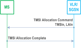
The allocation of a temporary identity is initiated by the VLR.
The VLR generates a new temporary identity (TMSIn) and stores the association of TMSIn and the permanent identity IMSI in its database. The TMSI should be unpredictable. The VLR then sends the TMSIn and (if necessary) the new location area identity LAIn to the user.
Upon receipt the user stores TMSIn and automatically removes the association with any previously allocatedTMSI. The user sends an acknowledgement back to the VLR.
Upon receipt of the acknowledgement the VLR removes the association with the old temporary identity TMSIo and the IMSI (if there was any) from its database.
6.1.3 Unacknowledged allocation of a temporary identity p. 18
If the serving network does not receive an acknowledgement of the successful allocation of a temporary identity from the user, the network shall maintain the association between the new temporary identity TMSIn and the IMSI and between the old temporary identity TMSIo (if there is any) and the IMSI.
For a user-originated transaction, the network shall allow the user to identify itself by either the old temporary identity TMSIo or the new temporary identity TMSIn. This allows the network to determine the temporary identity stored in the mobile station. The network shall subsequently delete the association between the other temporary identity and the IMSI, to allow the temporary identity to be allocated to another user.
For a network-originated transaction, the network shall identify the user by its permanent identity (IMSI). When radio contact has been established, the network shall instruct the user to delete any stored TMSI. When the network receives an acknowledgement from the user, the network shall delete the association between the IMSI and any TMSI to allow the released temporary identities to be allocated to other users.
Subsequently, in either of the cases above, the network may initiate the normal TMSI reallocation procedure.
Repeated failure of TMSI reallocation (passing a limit set by the operator) may be reported for O&M action.
6.1.4 Location update p. 19
In case a user identifies itself using a TMSIo/LAIo pair that was assigned by the visited VLRn the IMSI can normally be retrieved from the database. If this is not the case, the visited VLRn should request the user to identify itself by means of its permanent user identity. This mechanism is described in 6.2.
In case a user identifies itself using a TMSIo/LAIo pair that was not assigned by the visited VLRn and the visited VLRn and the previously visited VLRo exchange authentication data, the visited VLRn should request the previously visited VLRo to send the permanent user identity. This mechanism is described in 6.3.4, it is integrated in the mechanism for distribution of authentication data between VLRs. If the previously visited VLRo cannot be contacted or cannot retrieve the user identity, the visited VLRn should request the user to identify itself by means of its permanent user identity. This mechanism is described in 6.2.
6.2 Identification by a permanent identity p. 19
The mechanism described in here allows the identification of a user on the radio path by means of the permanent subscriber identity (IMSI).
The mechanism should be invoked by the serving network whenever the user cannot be identified by means of a temporary identity. In particular, it should be used when the user registers for the first time in a serving network, or when the serving network cannot retrieve the IMSI from the TMSI by which the user identifies itself on the radio path.
The mechanism is illustrated in Figure 4.
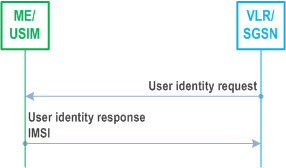
The mechanism is initiated by the visited VLR/SGSN that requests the user to send its permanent identity. The user's response contains the IMSI in cleartext. This represents a breach in the provision of user identity confidentiality.
6.3 Authentication and key agreement p. 19
6.3.1 General p. 19
The mechanism described here achieves mutual authentication by the user and the network showing knowledge of a secret key K which is shared between and available only to the USIM and the AuC in the user's HE. In addition the USIM and the HE keep track of counters SQN MS and SQN HE respectively to support network authentication. The sequence number SQN HE is an individual counter for each user and the sequence number SQN MS denotes the highest sequence number the USIM has accepted.
The method was chosen in such a way as to achieve maximum compatibility with the current GSM security architecture and facilitate migration from GSM to UMTS. The method is composed of a challenge/response protocol identical to the GSM subscriber authentication and key establishment protocol combined with a sequence number-based one-pass protocol for network authentication derived from ISO/IEC 9798-4 [10] (clause 5.1.1).
An overview of the mechanism is shown in Figure 5.
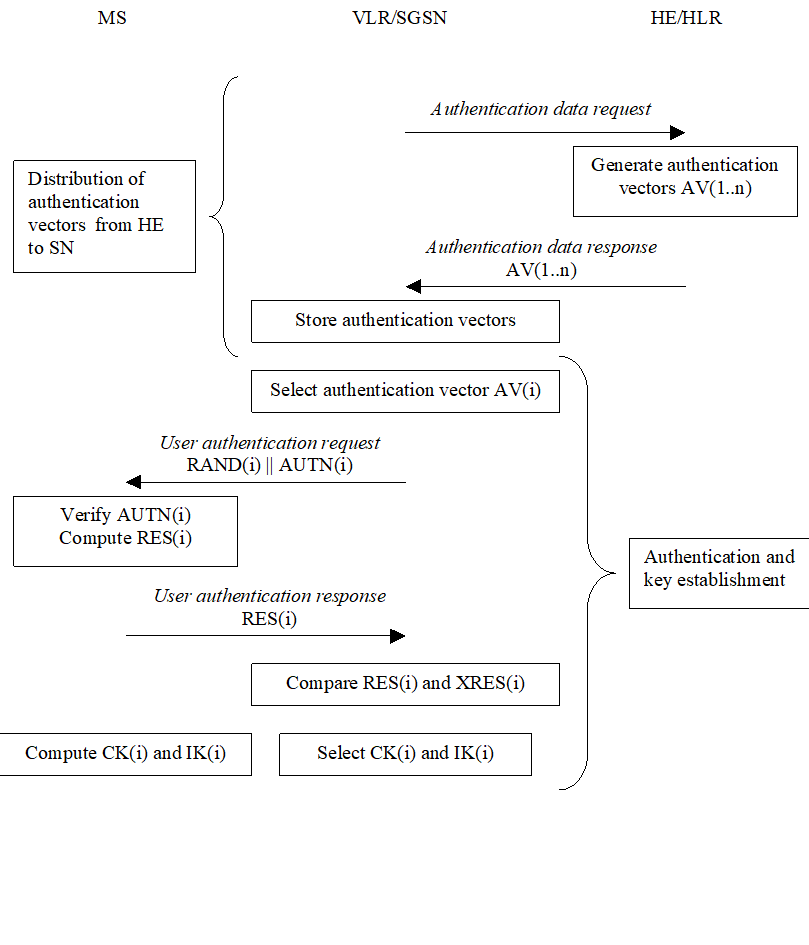
Upon receipt of a request from the VLR/SGSN, the HE/AuC sends an ordered array of n authentication vectors (the equivalent of a GSM "triplet") to the VLR/SGSN. The authentication vectors are ordered based on sequence number. Each authentication vector consists of the following components: a random number RAND, an expected response XRES, a cipher key CK, an integrity key IK and an authentication token AUTN. Each authentication vector is good for one authentication and key agreement between the VLR/SGSN and the USIM.
When the VLR/SGSN initiates an authentication and key agreement, it selects the next authentication vector from the ordered array and sends the parameters RAND and AUTN to the user. Authentication vectors in a particular node are used on a first-in / first-out basis. The USIM checks whether AUTN can be accepted and, if so, produces a response RES which is sent back to the VLR/SGSN. The USIM also computes CK and IK. The VLR/SGSN compares the received RES with XRES. If they match the VLR/SGSN considers the authentication and key agreement exchange to be successfully completed. The established keys CK and IK will then be transferred by the USIM and the VLR/SGSN to the entities which perform ciphering and integrity functions.
VLR/SGSNs can offer secure service even when HE/AuC links are unavailable by allowing them to use previously derived cipher and integrity keys for a user so that a secure connection can still be set up without the need for an authentication and key agreement. Authentication is in that case based on a shared integrity key, by means of data integrity protection of signalling messages (see 6.4).
The authenticating parties shall be the AuC of the user's HE (HE/AuC) and the USIM in the user's mobile station. The mechanism consists of the following procedures:
A procedure to distribute authentication information from the HE/AuC to the VLR/SGSN. This procedure is described in 6.3.2. The VLR/SGSN is assumed to be trusted by the user's HE to handle authentication information securely. It is also assumed that the intra-system links between the VLR/SGSN to the HE/AuC are adequately secure. It is further assumed that the user trusts the HE.
A procedure to mutually authenticate and establish new cipher and integrity keys between the VLR/SGSN and the MS. This procedure is described in 6.3.3.
A procedure to distribute authentication data from a previously visited VLR to the newly visited VLR. This procedure is described in 6.3.4. It is also assumed that the links between VLR/SGSNs are adequately secure.
6.3.2 Distribution of authentication data from HE to SN p. 21
The purpose of this procedure is to provide the VLR/SGSN with an array of fresh authentication vectors from the user's HE to perform a number of user authentications.

The VLR/SGSN invokes the procedures by requesting authentication vectors to the HE/AuC.
The authentication data request shall include the IMSI and the requesting node type (PS or CS).
Upon the receipt of the authentication data request from the VLR/SGSN, the HE may have pre-computed the required number of authentication vectors and retrieve them from the HLR database or may compute them on demand. The HE/AuC sends an authentication response back to the VLR/SGSN that contains an ordered array of n authentication vectors AV(1..n). The authentication vectors are ordered based on sequence number.
Figure 7 shows the generation of an authentication vector AV by the HE/AuC.
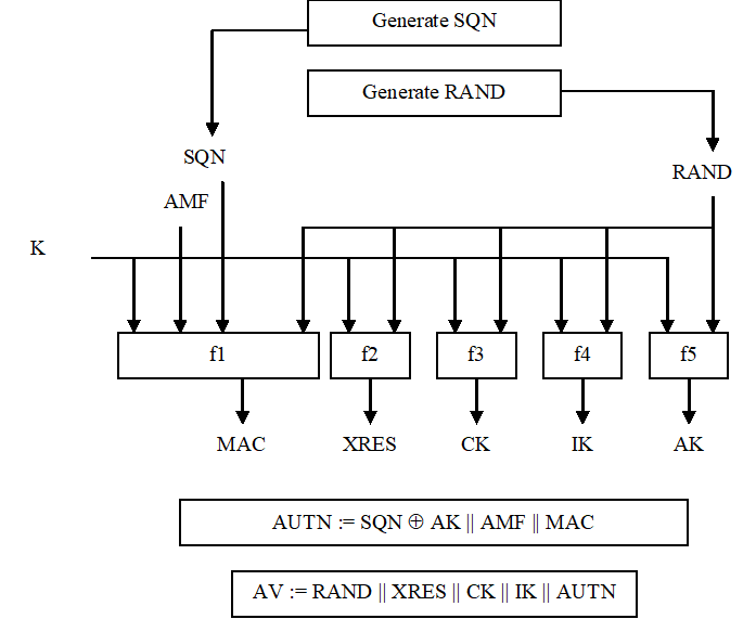
The HE/AuC starts with generating a fresh sequence number SQN and an unpredictable challenge RAND.
For each user the HE/AuC keeps track of a counter: SQN HE
The HE has some flexibility in the management of sequence numbers, but some requirements need to be fulfilled by the mechanism used:
- The generation mechanism shall allow a re-synchronisation procedure in the HE described in clause 6.3.5.
- In case the SQN exposes the identity and location of the user, the AK may be used as an anonymity key to conceal it.
- The generation mechanism shall allow protection against wrap around of the counter SQN in the USIM.
- a message authentication code MAC = f1K(SQN || RAND || AMF) where f1 is a message authentication function;
- an expected response XRES = f2K (RAND) where f2 is a (possibly truncated) message authentication function;
- a cipher key CK = f3K (RAND) where f3 is a key generating function;
- an integrity key IK = f4K (RAND) where f4 is a key generating function;
- an anonymity key AK = f5K (RAND) where f5 is a key generating function or f5 ≡ 0.
6.3.3 Authentication and key agreement p. 23
The purpose of this procedure is to authenticate the user and establish a new pair of cipher and integrity keys between the VLR/SGSN and the USIM. During the authentication, the USIM verifies the freshness of the authentication vector that is used.
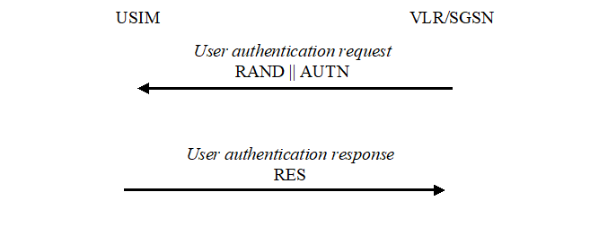
The VLR/SGSN invokes the procedure by selecting the next unused authentication vector from the ordered array of authentication vectors in the VLR/SGSN database. Authentication vectors in a particular node are used on a first-in / first-out basis. The VLR/SGSN sends to the USIM the random challenge RAND and an authentication token for network authentication AUTN from the selected authentication vector.
Upon receipt the user proceeds as shown in Figure 9.
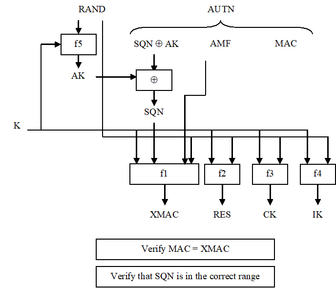
Upon receipt of RAND and AUTN the USIM first computes the anonymity key AK = f5K (RAND) and retrieves the sequence number SQN = (SQN * AK) * AK.
Next the USIM computes XMAC = f1K (SQN || RAND || AMF) and compares this with MAC which is included in AUTN. If they are different, the user sends an authentication failure message back to the VLR/SGSN with an indication of the cause and the user abandons the procedure. In this case, VLR/SGSN shall initiate an Authentication Failure Report procedure towards the HLR as specified in clause 6.3.6. VLR/SGSN may also decide to initiate a new identification and authentication procedure towards the user, cf. TS 24.008.
Next the USIM verifies that the received sequence number SQN is in the correct range.
If the USIM considers the sequence number to be not in the correct range, it sends synchronisation failure back to the VLR/SGSN including an appropriate parameter, and abandons the procedure.
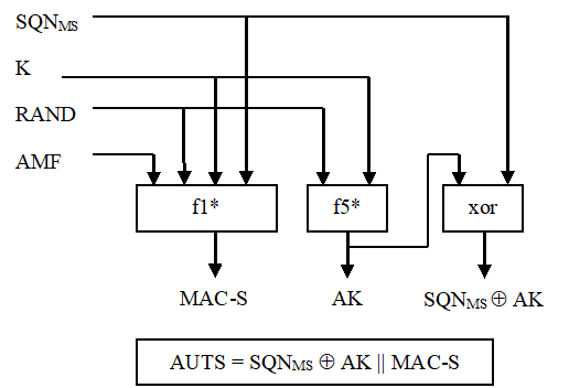
The synchronisation failure message contains the parameter AUTS. It is AUTS = Conc(SQN MS ) || MAC-S. Conc(SQN MS) = SQN MS ⊕ f5*K(RAND) is the concealed value of the counter SQN MS in the MS, and MAC-S = f1*K(SQN MS || RAND || AMF) where RAND is the random value received in the current user authentication request. f1* is a message authentication code (MAC) function with the property that no valuable information can be inferred from the function values of f1* about those of f1, ... , f5, f5* and vice versa. f5* is the key generating function used to compute AK in re-synchronisation procedures with the property that no valuable information can be inferred from the function values of f5* about those of f1, f1*, f2, ... , f5 and vice versa.
The AMF used to calculate MAC-S assumes a dummy value of all zeros so that it does not need to be transmitted in the clear in the re-synch message.
The construction of the parameter AUTS in shown in the following Figure 10:
If the sequence number is considered to be in the correct range however, the USIM computes RES = f2K (RAND) and includes this parameter in a user authentication response back to the VLR/SGSN. Finally the USIM computes the cipher key CK = f3K (RAND) and the integrity key IK = f4K (RAND). Note that if this is more efficient, RES, CK and IK could also be computed earlier at any time after receiving RAND. If the USIM also supports conversion function c3, it shall derive the 64-bit GSM cipher key Kc from the UMTS cipher/integrity keys CK and IK. UMTS keys are sent to the MS along with the derived 64-bit GSM key for UMTS-GSM interoperability purposes. USIM shall store original CK, IK until the next successful execution of AKA.
Upon receipt of user authentication response the VLR/SGSN compares RES with the expected response XRES from the selected authentication vector. If XRES equals RES then the authentication of the user has passed. The SGSN shall compute the 128-bit GSM ciphering key Kc 128 according to Annex B.5 if it is to use a 128-bit GSM ciphering algorithm. The VLR/MSC shall compute the 128-bit GSM ciphering key Kc 128 according to Annex B.5 if it signals a 128-bit GSM ciphering algorithm as a permitted GSM ciphering algorithm to the BSS. The VLR/SGSN also selects the appropriate cipher key CK and integrity key IK from the selected authentication vector. If XRES and RES are different, VLR/SGSN shall initiate an Authentication Failure Report procedure towards the HLR as specified in clause 6.3.6. VLR/SGSN may also decide to initiate a new identification and authentication procedure towards the user, cf. TS 24.008.
Re-use and re-transmission of (RAND, AUTN)
The verification of the SQN by the USIM will cause the MS to reject an attempt by the VLR/SGSN to re-use a quintet to establish a particular UMTS security context more than once. In general therefore the VLR/SGSN shall use a quintet only once.
There is one exception however: in the event that the VLR/SGSN has sent out an authentication request using a particular quintet and does not receive a response message (authentication response or authentication failure) from the MS, it may re-transmit the authentication request using the same quintet. However, as soon as a response message arrives no further re-transmissions are allowed. If after the initial transmission or after a series of re-transmissions no response arrives, retransmissions may be abandoned. If retransmissions are abandoned then the VLR/SGSN shall delete the quintet. At the MS side, in order to allow this re-transmission without causing additional re-synchronisation procedures, the ME shall store for the PS domain (and optionally the CS domain) the last received RAND as well as the corresponding RES, CK and IK. If the USIM returned SRES and Kc (for GSM access), the ME shall store these values. When the ME receives an authentication request and discovers that a RAND is repeated, it shall re-transmit the response. The ME shall delete the stored values RAND, RES and SRES (if they exist) as soon as the 3G security mode command or the GSM cipher mode command is received by the ME or the connection is aborted. If the ME can handle the retransmission mechanism for CS domain then it shall be able to handle the retransmission for both PS and CS domain simultaneously.
6.3.4 Distribution of IMSI and temporary authentication data within one serving network domain p. 26
The purpose of this procedure is to provide a newly visited VLR/SGSN with temporary authentication data from a previously visited VLR/SGSN within the same serving network domain.
The procedure is shown in Figure 11.
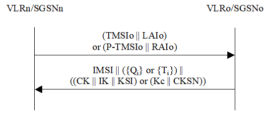
Figure 11: Distribution of IMSI and temporary authentication data within one serving network domain
(⇒ copy of original 3GPP image)
(⇒ copy of original 3GPP image)
The procedure shall be invoked by the newly visited VLRn/SGSNn after the receipt of a location update request (resp. routing area update request) from the user wherein the user is identified by means of a temporary user identity TMSIo (resp. P-TMSIo) and the location area identity LAIo (resp. routing area identity RAIo) under the jurisdiction of a previously visited VLRo/SGSNo that belongs to the same serving network domain as the newly visited VLRn/SGSNn.
The protocol steps are as follows:
- The VLRn/SGSNn sends a user identity request to the VLRo/SGSNo, this message contains TMSIo and LAIo (resp. P-TMSIo and RAIo).
-
The VLRo/SGSNo searches the user data in the database.
If the user is found, the VLRo/SGSNo shall send a user identity response back that:
- shall include the IMSI,
- may include a number of unused authentication vectors (quintets or triplets) ordered on a first-in / first-out basis, and
- may include the current security context data: CK, IK and KSI (UMTS) or Kc and CKSN (GSM).
- If the VLRn/SGSNn receives a user identity response with an IMSI, it creates an entry and stores any authentication vectors and any data on the current security context that may be included. If the VLRn/SGSNn receives a user identity response indicating that the user could not be identified, it shall initiate the user identification procedure described in 6.2.
6.3.5 Re-synchronisation procedure p. 27
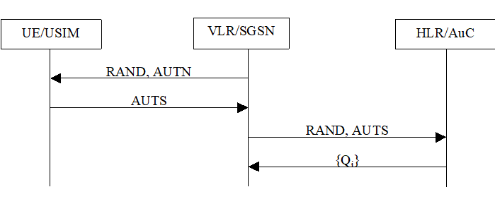
A VLR/SGSN may send two types of authentication data requests to the HE/AuC, the (regular) one described in subclause 6.3.2 and one used in case of synchronisation failures, described in this subclause.
Upon receiving a synchronisation failure message from the user, the VLR/SGSN sends an authentication data request with a "synchronisation failure indication" to the HE/AuC, together with the parameters:
- RAND sent to the MS in the preceding user authentication request, and
- AUTS received by the VLR/SGSN in the response to that request, as described in subclause 6.3.3.
- The HE/AuC retrieves SQN MS from Conc(SQN MS) by computing Conc(SQN MS) * f5*K(RAND).
- The HE/AuC checks if SQN HE is in the correct range, i.e. if the next sequence number generated SQN HE using would be accepted by the USIM.
- If SQN HE is in the correct range then the HE/AuC continues with step (6), otherwise it continues with step (4).
- The HE/AuC verifies AUTS (cf. subclause 6.3.3).
- If the verification is successful the HE/AuC resets the value of the counter SQN HE to SQN MS.
- The HE/AuC sends an authentication data response with a new batch of authentication vectors to the VLR/SGSN. If the counter SQN HE was not reset then these authentication vectors can be taken from storage, otherwise they are newly generated after resetting SQN HE. In order to reduce the real-time computation burden on the HE/AuC, the HE/AuC may also send only a single authentication vector in the latter case.
6.3.6 Reporting authentication failures from the SGSN/VLR to the HLR p. 28
The purpose of this procedure is to provide a mechanism for reporting authentication failures from the serving environment back to the home environment.
The procedure is shown in Figure 13.
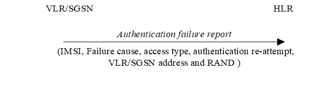
The procedure is invoked by the serving network VLR/SGSN when the authentication procedure fails. The authentication failure report shall contain:
- Subscriber identity;
- Failure cause code. The possible failure causes are either that the network signature was wrong or that the user response was wrong;
- Access type. This indicates the type of access that initiated the authentication procedure;
- Authentication re-attempt. This indicates whether the failure was produced in a normal authentication attempt or it was due to an authentication reattempt (there was a previous unsuccessful authentication). Details are provided in subclause 6.3.6.1;
- VLR/SGSN address;
- RAND. This number uniquely identifies the specific AV that failed authentication.
6.3.6.1 Authentication re-attempt |R6| p. 28
The serving network sets the Authentication re-attempt to "true" if the second authentication described in the following cases results in an authentication failure report:
- authentication with (P-)TMSI failed in MS (reject cause 'MAC failure') and new authentication procedure (re-attempt) is taken because an IMSI obtained by the followed IDENTITY REQUEST procedure does not match to the original IMSI that linked with (P-)TMSI.
- authentication failed in MS (reject cause 'GSM authentication unacceptable') and new authentication procedure (re-attempt) is taken after MSC obtains UMTS authentication vectors from HLR.
- authentication failed in MS (reject cause 'synch failure') and new authentication procedure (re-attempt) is taken after MSC obtains new authentication vectors from HLR for re-synchronisation.
- SRES mismatches with (P-)TMSI in VLR/SGSN and new authentication procedure (re-attempt) is taken because an IMSI obtained by the followed IDENTITY REQUEST procedure does not match to the original IMSI that linked with (P-)TMSI.
6.3.7 Length of authentication parameters p. 29
The authentication key (K) shall have a length of 128 bits or 256 bits.
The random challenge (RAND) shall have a length of 128 bits.
Sequence numbers (SQN) shall have a length of 48 bits.
The anonymity key (AK) shall have a length of 48 bits.
The authentication management field (AMF) shall have a length of 16 bits.
The message authentication codes MAC in AUTN and MAC-S in AUTS shall have a length of 64 bits.
The cipher key (CK) shall have a length of 128 bits.
The integrity key (IK) shall have a length of 128 bits.
The authentication response (RES) shall have a variable length of 4-16 octets.