Content for TS 24.502 Word version: 19.0.0
9.3 IETF RFC coding information
9.3.1 IKEv2 Notify payloads
9.3.1.1 5G_QOS_INFO Notify payload
9.3.1.2 NAS_IP4_ADDRESS Notify payload
9.3.1.3 NAS_IP6_ADDRESS Notify payload
9.3.1.4 UP_IP4_ADDRESS Notify payload
9.3.1.5 UP_IP6_ADDRESS Notify payload
9.3.1.6 NAS_TCP_PORT Notify payload
9.3.1.7 N3GPP_BACKOFF_TIMER Notify payload
9.3.1.8 UP_SA_INFO Notify payload
...
...
9.3 IETF RFC coding information p. 87
9.3.1 IKEv2 Notify payloads p. 87
9.3.1.1 5G_QOS_INFO Notify payload p. 87
The 5G_QOS_INFO Notify payload is used to indicate:
- the PDU session identity;
- zero or more QFIs;
- optionally a DSCP value associated with the child SA;
- whether the child SA is the default child SA; and
- if trusted non-3GPP access, Additional QoS Information, or if untrusted non-3GPP access, optionally Additional QoS Information.
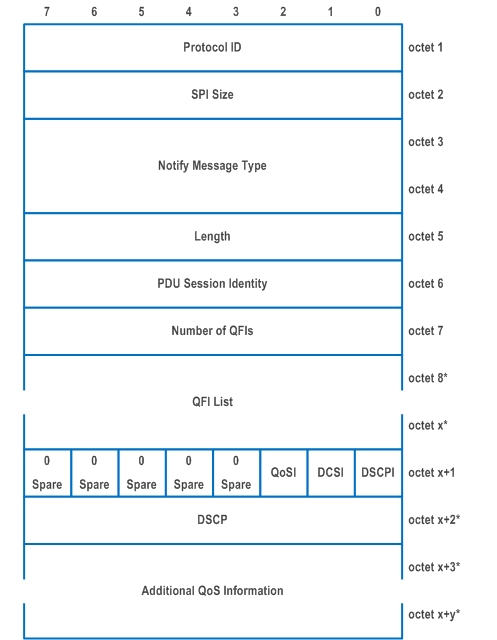
| Octet 1 is defined in RFC 7296. | |
| Octet 2 is the SPI Size field. It is set to 0 and there is no Security Parameter Index field. | |
| Octet 3 and Octet 4 is the Notify Message Type field. The Notify Message Type field is set to value 55501 to indicate the 5G_QOS_INFO. | |
| Octet 5 is the Length field. This field indicates the length in octets of the 5G_QOS_INFO Notify payload starting from octet 6. | |
| Octet 6 is the PDU Session Identity field. This field indicates the PDU session associated with the child SA for user plane. | |
| Octet 7 is the Number of QFIs field. This field indicates the number of QFIs in the QFI list. | |
| Octet 8 to octet x is the QFI List field. This field indicates those QoS flows associated with the child SA. Every QFI is coded as the QFI field in the QoS rule defined in TS 24.501. | |
| Octet x+1, bit 0 is the DSCP included field (DSCPI). | |
| 0 | DSCP field is not included. |
| 1 | DSCP field is included. |
| Octet x+1, bit 1 is the indication of whether the child SA is the default child SA (DCSI). | |
| 0 | the child SA is not the default child SA. |
| 1 | the child SA is the default child SA. |
| Octet x+1, bit 2 is the Additional QoS Information indication field (QoSI) | |
| 0 | Additional QoS Information is not included. |
| 1 | Additional QoS Information is included. |
| Octet x+2 is the DSCP field. If included, this field indicates the DSCP marking for all IP packets sent over this child SA. | |
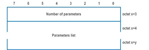
| Octet x+3 to octet x+y is the Additional QoS Information field which is included if the access network is the trusted non-3GPP access network, and is optionally included if the access network is the untrusted non-3GPP access network. This field is encoded as defined in Table 9.3.1.1-2. | |
| Octet x+3 is number of parameters | |
| The number of parameters field contains the binary coding for the number of parameters in the parameters list field. The number of parameters field is encoded in bits 7 through 0 of octet x+3 where bit 7 is the most significant and bit 0 is the least significant bit. | |
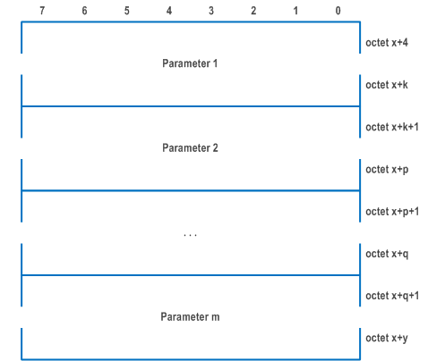
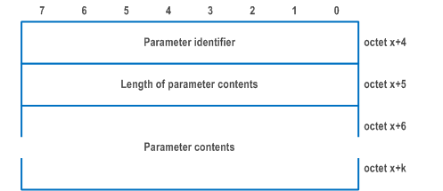
| The parameter identifier field is used to identify each parameter included in the parameters list and it contains the binary coding of the parameter identifier. Bit 7 of the parameter identifier field contains the most significant bit and bit 0 contains the least significant bit. The following parameter identifiers are specified: | |
| Bits
7 6 5 4 3 2 1 0 | |
| 0 0 0 0 0 0 0 1 | QoS characteristics; |
| 0 0 0 0 0 0 1 0 | Maximum Flow Bit Rate downlink (MFBR downlink); |
| 0 0 0 0 0 0 1 1 | Maximum Flow Bit Rate uplink (MFBR uplink); |
| 0 0 0 0 0 1 0 0 | Guaranteed Flow Bit Rate downlink (GFBR downlink); |
| 0 0 0 0 0 1 0 1 | Guaranteed Flow Bit Rate uplink (GFBR uplink); |
| 0 0 0 0 0 1 1 0 | Notification Control; |
| 0 0 0 0 0 1 1 1 | Maximum Packet Loss Rate downlink; and |
| 0 0 0 0 1 0 0 0 | Maximum Packet Loss Rate uplink. |
| All other values are spare. | |
| If the parameters list contains a parameter identifier that is not supported by the receiving entity the corresponding parameter shall be discarded. | |
| If the parameter identifier indicates QoS characteristics, the parameter contents field contains the following representation: | |
| Octet 1 is the resource type with binary representation: | |
| Bits
7 6 5 4 3 2 1 0 | |
| 0 0 0 0 0 0 0 0 | GBR |
| 0 0 0 0 0 0 0 1 | Delayed critical GBR |
| 0 0 0 0 0 0 1 0 | Non GBR |
| All other values are spare. | |
| Octet 2 is the priority level with 1 as the highest priority and 127 as the lowest priority ((see clause 9.3.1.84 in TS 38.413, see NOTE), and the binary representation is: | |
| Bits
7 6 5 4 3 2 1 0 | |
| 0 0 0 0 0 0 0 1 | |
| thru | |
| 0 1 1 1 1 1 1 1 | |
| All other values are spare. | |
| Octets 3 and 4 are the packet delay budget and is a factor of 0.5ms (see clause 9.3.1.80 in TS 38.413, see NOTE), where the factor has the following binary representation: | |
| Bits
7 6 5 4 3 2 1 0 7 6 5 4 3 2 1 0 | |
| 0 0 0 0 0 0 0 0 0 0 0 0 0 0 0 0 | |
| thru | |
| 0 0 0 0 0 0 1 1 1 1 1 1 1 1 1 1 | |
| All other values are spare. | |
| Octets 5 and 6 are the packet error rate where octet 5 is scalar and octet 6 represents exponent. The packet error rate is calculated as {scalar x10 - exponent} (see clause 9.3.1.81 of TS 38.413) The binary representation of scalar and exponent are: | |
| Bits
7 6 5 4 3 2 1 0 | |
| 0 0 0 0 0 0 0 0 | |
| thru | |
| 0 0 0 0 1 0 0 1 | |
| All other values are spare. | |
| Octets 7 and 8 are the averaging window and is included if the resource type is GBR. Averaging window is a factor of 0.5ms with default value of 2000ms (see clause 9.3.1.82 in TS 38.413, see NOTE), where the factor has the following binary representation: | |
| Bits
7 6 5 4 3 2 1 0 7 6 5 4 3 2 1 0 | |
| 0 0 0 0 0 0 0 0 0 0 0 0 0 0 0 0 | |
| thru | |
| 0 0 0 0 1 1 1 1 1 1 1 1 1 1 1 1 | |
| All other values are spare. | |
| Octets 9 and 10 are the maximum data burst volume and is included if the resource type is delayed critical GBR. Maximum data burst volume is the maximum number of the bytes for the data volume (see clause 9.3.1.83 of TS 38.413, see NOTE), where the maximum number of bytes has the following binary representation: | |
| Bits
7 6 5 4 3 2 1 0 7 6 5 4 3 2 1 0 | |
| 0 0 0 0 0 0 0 0 0 0 0 0 0 0 0 0 | |
| thru | |
| 0 0 0 0 1 1 1 1 1 1 1 1 1 1 1 1 | |
| All other values are spare. | |
| For GBR and delayed critical GBR resource types if the parameter identifier indicates " GFBR downlink", the parameter contents field contains one octet indicating the unit of the guaranteed flow bit rate for downlink followed by two octets containing the value of the guaranteed flow bit rate for downlink. | |
| Unit of the guaranteed flow bit rate for downlink (octet 1) | |
| Bits
7 6 5 4 3 2 1 0 | |
| 0 0 0 0 0 0 0 0 | value is not used |
| 0 0 0 0 0 0 0 1 | value is incremented in multiples of 1 Kbps |
| 0 0 0 0 0 0 1 0 | value is incremented in multiples of 4 Kbps |
| 0 0 0 0 0 0 1 1 | value is incremented in multiples of 16 Kbps |
| 0 0 0 0 0 1 0 0 | value is incremented in multiples of 64 Kbps |
| 0 0 0 0 0 1 0 1 | value is incremented in multiples of 256 Kbps |
| 0 0 0 0 0 1 1 0 | value is incremented in multiples of 1 Mbps |
| 0 0 0 0 0 1 1 1 | value is incremented in multiples of 4 Mbps |
| 0 0 0 0 1 0 0 0 | value is incremented in multiples of 16 Mbps |
| 0 0 0 0 1 0 0 1 | value is incremented in multiples of 64 Mbps |
| 0 0 0 0 1 0 1 0 | value is incremented in multiples of 256 Mbps |
| 0 0 0 0 1 0 1 1 | value is incremented in multiples of 1 Gbps |
| 0 0 0 0 1 1 0 0 | value is incremented in multiples of 4 Gbps |
| 0 0 0 0 1 1 0 1 | value is incremented in multiples of 16 Gbps |
| 0 0 0 0 1 1 1 0 | value is incremented in multiples of 64 Gbps |
| 0 0 0 0 1 1 1 1 | value is incremented in multiples of 256 Gbps |
| 0 0 0 1 0 0 0 0 | value is incremented in multiples of 1 Tbps |
| 0 0 0 1 0 0 0 1 | value is incremented in multiples of 4 Tbps |
| 0 0 0 1 0 0 1 0 | value is incremented in multiples of 16 Tbps |
| 0 0 0 1 0 0 1 1 | value is incremented in multiples of 64 Tbps |
| 0 0 0 1 0 1 0 0 | value is incremented in multiples of 256 Tbps |
| 0 0 0 1 0 1 0 1 | value is incremented in multiples of 1 Pbps |
| 0 0 0 1 0 1 1 0 | value is incremented in multiples of 4 Pbps |
| 0 0 0 1 0 1 1 1 | value is incremented in multiples of 16 Pbps |
| 0 0 0 1 1 0 0 0 | value is incremented in multiples of 64 Pbps |
| 0 0 0 1 1 0 0 1 | value is incremented in multiples of 256 Pbps |
| Other values shall be interpreted as multiples of 256 Pbps in this version of the protocol. | |
| Value of the guaranteed flow bit rate for downlink (octets 2 and 3) | |
| Octets 2 and 3 represent the binary coded value of the guaranteed flow bit rate for downlink in units defined by the unit of the guaranteed flow bit rate for downlink. | |
| For GBR and delayed critical GBR resource types if the parameter identifier indicates "GFBR uplink", the parameter contents field contains one octet indicating the unit of the guaranteed flow bit rate for uplink followed by two octets containing the value of the guaranteed flow bit rate for uplink. | |
| Unit of the guaranteed flow bit rate for uplink (octet 1) | |
| The coding is identical to that of the unit of the guaranteed flow bit rate for downlink. | |
| Value of the guaranteed flow bit rate for uplink (octets 2 and 3) | |
| Octets 2 and 3 represent the binary coded value of the guaranteed flow bit rate for uplink in units defined by the unit of the guaranteed flow bit rate for uplink. | |
| For GBR and delayed critical GBR resource types if the parameter identifier indicates "MFBR downlink", the parameter contents field contains one octet indicating the unit of the maximum flow bit rate for downlink followed by two octets containing the value of maximum flow bit rate for downlink. | |
| Unit of the maximum flow bit rate for downlink (octet 1) | |
| The coding is identical to that of the unit of the guaranteed flow bit rate for downlink. | |
| Value of the maximum flow bit rate for downlink (octets 2 and 3) | |
| Octets 2 and 3 represent the binary coded value of the maximum flow bit rate for downlink in units defined by the unit of the maximum flow bit rate for downlink. | |
| For GBR and delayed critical GBR resource types if the parameter identifier indicates "MFBR uplink", the parameter contents field contains one octet indicating the unit of the maximum flow bit rate for uplink followed by two octets containing the value of the maximum flow bit rate for downlink. | |
| Unit of the maximum flow bit rate for uplink (octet 1) | |
| The coding is identical to that of the unit of the guaranteed flow bit rate for uplink. | |
| Value of the maximum flow bit rate for uplink (octets 2 and 3) | |
| Octets 2 and 3 represent the binary coded value of the maximum flow bit rate for uplink in units defined by the unit of the maximum flow bit rate for uplink. | |
| For GBR and delayed critical GBR resource types if the parameter identifier indicates "Notification Control", the parameter identifier shall be ignored in this release. | |
| For GBR and delayed critical GBR resource types if the parameter identifier indicates "Maximum Packet Loss Rate downlink", the parameter contents field contains the ratio of the lost downlink packets per number of downlink packets sent, expressed in tenth of percent (see clause 9.3.1.79 in TS 38.413, see NOTE), with the binary representation: | |
| Bits
7 6 5 4 3 2 1 0 7 6 5 4 3 2 1 0 | |
| 0 0 0 0 0 0 0 0 0 0 0 0 0 0 0 0 | |
| thru | |
| 0 0 0 0 0 0 1 1 1 1 1 0 1 0 0 0 | |
| All other values are spare. | |
| For GBR and delayed critical GBR resource types if the parameter identifier indicates "Maximum Packet Loss Rate uplink", the parameter contents field contains the ratio of the lost uplink packets per number of uplink packets sent, expressed in tenth of percent (see clause 9.3.1.79 in TS 38.413), with the binary representation: | |
| Bits
7 6 5 4 3 2 1 0 7 6 5 4 3 2 1 0 | |
| 0 0 0 0 0 0 0 0 0 0 0 0 0 0 0 0 | |
| thru | |
| 0 0 0 0 0 0 1 1 1 1 1 0 1 0 0 0 | |
| All other values are spare. | |
| NOTE: | |
9.3.1.2 NAS_IP4_ADDRESS Notify payload p. 94
The NAS_IP4_ADDRESS Notify payload is used to indicate the inner IPv4 address of the N3IWF for untrusted non-3GPP access or the TNGF for trusted non-3GPP access for NAS message transport.
The NAS_IP4_ADDRESS Notify payload is coded according to Figure 9.3.1.2-1 and Table 9.3.1.2-1.
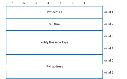
| Octet 1 is defined in RFC 7296. | |
| Octet 2 is SPI Size field. It is set to 0 and there is no Security Parameter Index field. | |
| Octet 3 and Octet 4 is the Notify Message Type field. The Notify Message Type field is set to value 55502 to indicate the NAS_IP4_ADDRESS. | |
| Octet 5 to octet 8 is the IPv4 address field. The IPv4 address field contains the inner IPv4 address of the N3IWF for untrusted non-3GPP access or the TNGF for trusted non-3GPP access for NAS message transport. | |
9.3.1.3 NAS_IP6_ADDRESS Notify payload p. 94
The NAS_IP6_ADDRESS Notify payload is used to indicate the inner IPv6 address of the N3IWF for untrusted non-3GPP access or the TNGF for trusted non-3GPP access for NAS message transport.
The NAS_IP6_ADDRESS Notify payload is coded according to Figure 9.3.1.3-1 and Table 9.3.1.3-1.
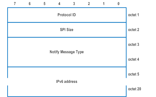
| Octet 1 is defined in RFC 7296. | |
| Octet 2 is SPI Size field. It is set to 0 and there is no Security Parameter Index field. | |
| Octet 3 and Octet 4 is the Notify Message Type field. The Notify Message Type field is set to value 55503 to indicate the NAS_IP6_ADDRESS. | |
| Octet 5 to octet 20 is the IPv6 address field. The IPv6 address field contains the inner IPv6 address of the N3IWF for untrusted non-3GPP access or the TNGF for trusted non-3GPP access for NAS message transport. | |
9.3.1.4 UP_IP4_ADDRESS Notify payload p. 95
The UP_IP4_ADDRESS Notify payload is used to indicate the inner IPv4 address of the N3IWF for untrusted non-3GPP access or the TNGF for trusted on-3GPP access for GRE user data packet transport.
The UP_IP4_ADDRESS Notify payload is coded according to Figure 9.3.1.4-1 and Table 9.3.1.4-1.
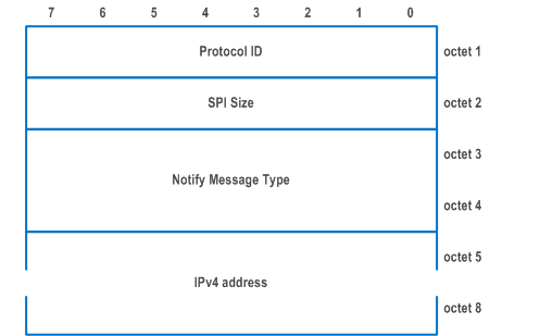
| Octet 1 is defined in RFC 7296. | |
| Octet 2 is SPI Size field. It is set to 0 and there is no Security Parameter Index field. | |
| Octet 3 and Octet 4 is the Notify Message Type field. The Notify Message Type field is set to value 55504 to indicate the UP_IP4_ADDRESS. | |
| Octet 5 to octet 8 is the IPv4 address field. The IPv4 address field contains the inner IPv4 address of the N3IWF for untrusted non-3GPP access or the TNGF for trusted on-3GPP access for GRE user data packet transport. | |
9.3.1.5 UP_IP6_ADDRESS Notify payload p. 96
The UP_IP6_ADDRESS Notify payload is used to indicate the inner IPv6 address of the N3IWF for untrusted non-3GPP access or the TNGF for trusted non-3GPP access for GRE user data packet transport.
The UP_IP6_ADDRESS Notify payload is coded according to Figure 9.3.1.5-1 and Table 9.3.1.5-1.
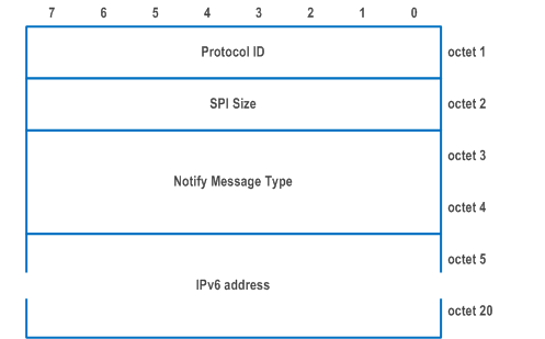
| Octet 1 is defined in RFC 7296. | |
| Octet 2 is SPI Size field. It is set to 0 and there is no Security Parameter Index field. | |
| Octet 3 and Octet 4 is the Notify Message Type field. The Notify Message Type field is set to value 55505 to indicate the UP_IP6_ADDRESS. | |
| Octet 5 to octet 20 is the IPv6 address field. The IPv6 address field contains the inner IPv6 address of the N3IWF for untrusted non-3GPP access or the TNGF for trusted non-3GPP access for GRE user data packet transport. | |
9.3.1.6 NAS_TCP_PORT Notify payload p. 96
The NAS_TCP_PORT Notify payload is used to indicate the port number for the connection of the inner TCP transport protocol for the NAS message transport.
The NAS_TCP_PORT Notify payload is coded according to Figure 9.3.1.6-1 and Table 9.3.1.6-1.
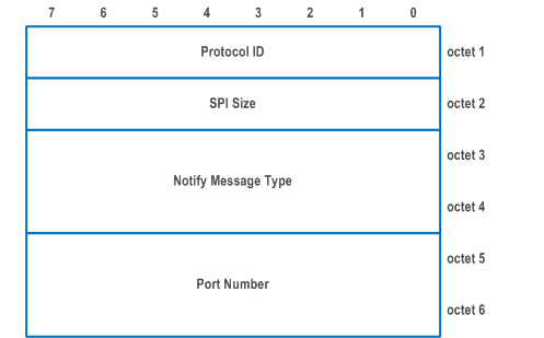
| Octet 1 is defined in RFC 7296. | |
| Octet 2 is SPI Size field. It is set to 0 and there is no Security Parameter Index field. | |
| Octet 3 and Octet 4 is the Notify Message Type field. The Notify Message Type field is set to value 55506 to indicate the NAS_TCP_PORT. | |
| Octet 5 and octet 6 are the Port Number field which contains the port number of the connection for the inner TCP transport protocol for the NAS message transport. | |
9.3.1.7 N3GPP_BACKOFF_TIMER Notify payload p. 97
The N3GPP_BACKOFF_TIMER Notify payload is used to indicate the value of the back-off timer.
The N3GPP_BACKOFF_TIMER Notify payload is coded according to Figure 9.3.1.7-1 and Table 9.3.1.7-1.
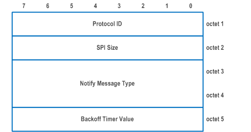
| Octet 1 is defined in RFC 7296. | |
| Octet 2 is SPI Size field. It is set to 0 and there is no Security Parameter Index field. | |
| Octet 3 and Octet 4 is the Notify Message Type field. The Notify Message Type field is set to value 55507 to indicate the N3GPP_BACKOFF_TIMER. | |
| Octet 5 is the Backoff Timer Value field. This field indicates the value of the back-off timer. It is coded as the value part (as specified in TS 24.007 for type 4 IE) of the GPRS timer 3 information element defined in clause 10.5.7.4a of TS 24.008 (NOTE). | |
|
NOTE:
The GPRS Timer 3 IEI field and the length of GPRS Timer 3 contents field of the GPRS timer 3 information element are not included in the value of the back-off timer.
|
9.3.1.8 UP_SA_INFO Notify payload |R18| p. 97
The UP_SA_INFO Notify payload is used to indicate the SPI of the inbound ESP packets of the user plane IPsec SA.
The UP_SA_INFO Notify payload is coded according to Figure 9.3.1.8-1 and Table 9.3.1.8-1.
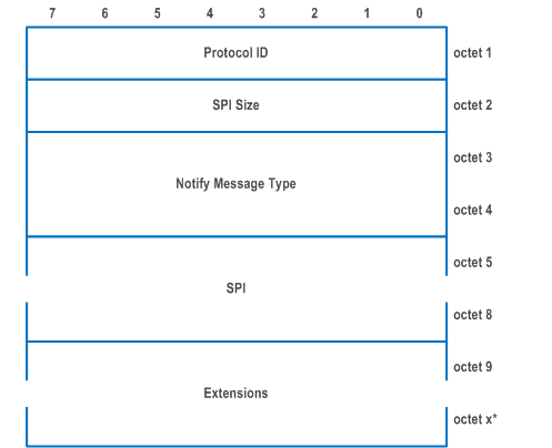
| Octet 1 is defined in RFC 7296. | |
| Octet 2 is the SPI Size field. This field indicates the length of the SPI field in octets. | |
| Octet 3 and octet 4 is the Notify Message Type field. The Notify Message Type field is set to value 55508 to indicate the UP_SA_INFO. | |
| Octet 5 to octet 8 is the SPI field. This field indicates the SPI of the inbound ESP packets (i.e., the ESP packets that the sender of UP_SA_INFO Notify payload is expected to receive) of the user plane IPsec SA specified in RFC 7296. | |
| Octet 9 to octet x is an optional Extensions field reserved for future use. | |