Content for TS 23.682 Word version: 19.1.0
1…
4.2
4.3…
4.4…
4.5…
4.5.7…
4.5.14…
4.6…
5…
5.3…
5.5…
5.6…
5.6.2…
5.6.6…
5.7…
5.8…
5.9…
5.13…
5.14…
5.15
5.16
5.17…
5.18
5.19…
A…
C…
C Triggering with OMA Push
C.1 General
C.2 Triggering flow using Service Loading
D Device triggering using direct model over user plane
$ Change history
C Triggering with OMA Push p. 130
C.1 General p. 130
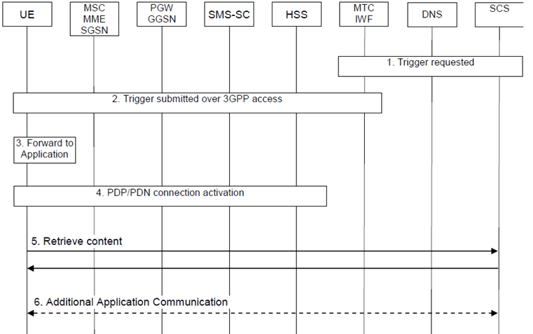
The 3GPP Device Trigger function enables a transport of application defined triggers to be delivered from a Service Capability Server (SCS) towards the UE. One defined application trigger framework is OMA Push Architecture [20]. OMA Push defined messages can be carried as payload in the Device Trigger message.
C.2 Triggering flow using Service Loading p. 130

Step 1.
The SCS generates content (e.g. an MTC application specific command) and a URI towards the content (or receives a URI towards content from another source) and then the SCS (performing OMA Push Proxy Gateway functionality) generates a Push Message [19] with the PDU set according to Service Loading [17], and sends a trigger request over Tsp according to clause 5.2.1.
Step 2.
The MTC-IWF receives the trigger request and sends it according to clause 5.2.1.
Step 3.
The UE SMS dispatcher receives the SMS and routes it to the OMA Push Client which has registered for the triggering routing identifier (e.g. SMS Application port). The OMA Push Client, optionally validates the source (using whitelist defined in OMA Push Management Object [18]) and then forwards the trigger using the Application-Id (e.g. to the M2M Service Capability Layer).
Step 4.
The UE activates a PDP/PDN connection.
Step 5.
The content described as part of the URI is retrieved (retrieval of content is mandatory for content type Service Loading [17]).
Step 6.
Based on the content retrieved the addressed Application may perform additional actions (e.g. the M2M Service Capability Layer may convey the information to an M2M Application addressed as part of the "command" retrieved, within the same or in a different physical device), but this is outside scope of 3GPP standardisation.
D Device triggering using direct model over user plane p. 132
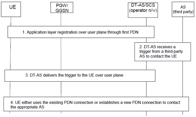
The following flow shows an example of device triggering using direct model over user plane. In this example, an application in the UE explicitly registers with a DT-AS/SCS (Device Trigger Application Server) in the home operator's network using an existing PDN connection (e.g. default PDN connection). The DT-AS uses the information from the application registration (such as IP address, port, protocol, etc.) to deliver the incoming device triggers, forwarded by another AS (e.g. third party AS) or itself, to the UE through the user plane. Once the UE receives the trigger, the UE either uses the existing PDN connection or the UE sets up a new PDN connection to the appropriate APN to contact the third-party Application Server.

Step 1.
The UE/MTC application registers with the DT-AS in an operator's network using an existing PDN connection (for e.g. default PDN). The registration information, for example, could include the IPv4/IPv6 address and the port number where the application is reachable.
Step 2.
The DT-AS receives a trigger from a third-party AS to reach the UE.
Step 3.
The DT-AS delivers the trigger to the UE over the user plane.
Step 4.
The UE either uses the existing PDN connection or sets up a new PDN connection using the appropriate APN to contact the third-party AS.