Content for TS 23.379 Word version: 19.5.0
1…
7…
10…
10.5…
10.6…
10.6.2.3…
10.6.2.4…
10.6.2.5…
10.6.2.6…
10.6.2.9…
10.6.3…
10.7…
10.7.3…
10.7.5…
10.7.6…
10.9…
10.9.1.3.3…
10.9.1.4…
10.9.2…
10.10…
10.12…
10.19…
10.19.3…
10.19.3.1.4…
10.19.3.2…
10.19.3.2.4…
10.19.3.2.6…
A…
7 Functional model
7.1 General
7.2 Description of the planes
7.3 Functional model description
7.4 Functional entities description
7.5 Reference points
8 Identities
9 Application of functional model to deployments
...
...
7 Functional model p. 19
7.1 General p. 19
The functional model for the support of MCPTT is defined as a series of planes to allow for the breakdown of the architectural description.
7.2 Description of the planes p. 20
The description of the planes and the relationship between the planes are contained in the common functional architecture to support MC services in TS 23.280.
7.3 Functional model description p. 20
7.3.1 On-network functional model p. 20
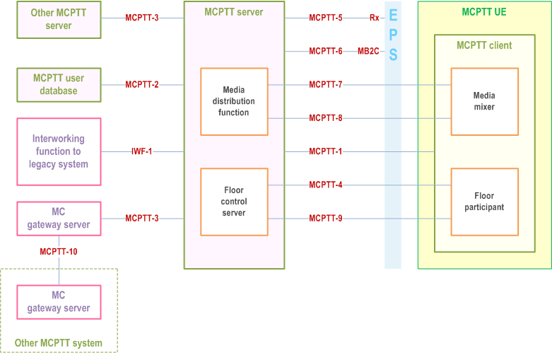
Figure 7.3.1-1 shows the functional model for the application plane of the MCPTT service.

In the model shown in Figure 7.3.1-1, the following apply:
- The MCPTT server is an instantiation of a MC service server in accordance with TS 23.280.
- The MCPTT server is an instantiation of a GCS AS in accordance with TS 23.468.
- MCPTT-9 carries multicast floor control signalling between the floor control server of the MCPTT server and the floor participant of the MCPTT UE.
- MCPTT-4 carries unicast floor control signalling between the floor control server of the MCPTT server and the floor participant of the MCPTT UE.
- MCPTT-7 carries unicast media between the media distribution function of the MCPTT server and the media mixer of the MCPTT UE.
- MCPTT-8 carries multicast media from the media distribution function of the MCPTT server to the media mixer of the MCPTT UE.

7.3.2 Off-network functional model p. 21
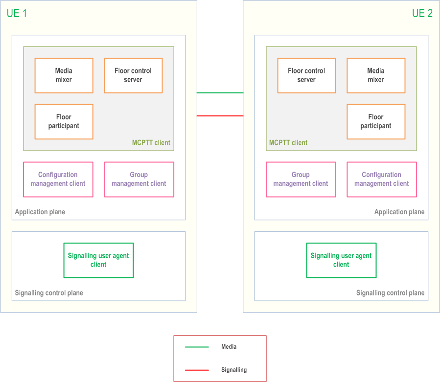
Figure 7.3.2-1 shows the functional model for off-network operation of MCPTT service.

7.4 Functional entities description p. 22
7.4.1 General p. 22
Each subclause is a description of a functional entity and does not imply a physical entity.
7.4.2 Application plane of MCPTT service p. 22
7.4.2.1 General p. 22
Entities within the application plane of MCPTT service provide application control, media control and distribution functions.
7.4.2.2 Common services core p. 22
The description of the common services core entities are contained in common functional architecture to support MC services in TS 23.280.
7.4.2.3 MCPTT application service p. 22
7.4.2.3.1 MCPTT client p. 22
The MCPTT client functional entity acts as the user agent for all MCPTT application transactions. The client reports the information of where the client is currently located.
7.4.2.3.2 MCPTT server p. 22
The MCPTT server functional entity provides centralised support for MCPTT services.
All the MCPTT clients supporting users belonging to a single group are required to use the same MCPTT server for that group. An MCPTT client supporting a user involved in multiple groups can have relationships with multiple MCPTT servers.
The MCPTT server functional entity represents a specific instantiation of the GCS AS described in TS 23.468 to control multicast and unicast operations for group communications.
The MCPTT server functional entity is supported by the SIP AS, HTTP client and HTTP server functional entities of the signalling control plane.
By assuming the role of a GCS AS, the MCPTT server functional entity is responsible for:
- requesting the allocation of multicast resources utilizing the media distribution function;
- announcing the association of multicast resources to calls to MCPTT UEs;
- determining for each MCPTT UE involved in a given call whether to use unicast or multicast transport;
- announcing the assignment of multicast transport for specific calls to MCPTT UEs; and
- informing the media distribution function of the media streams requiring support for a given call.
- call control (e.g. policy enforcement for participation in the MCPTT group calls) towards all the MCPTT users of the group call and private call;
- interfacing with the group management server for group policy and affiliation status information of this MCPTT server's served affiliated users;
- enforcing functional alias priority handling;
- managing floor control entity in a group call and private call; and
- managing media handling entity in call i.e. conferencing, transcoding.
- interfacing with the functional alias management server for functional alias policy from the functional alias configuration;
- functional alias activation, deactivation, take over and interrogation support for MCPTT user.
- call control (e.g. authorization for participation in the MCPTT group calls) to its MCPTT users for group call and private call;
- group affiliation support for MCPTT user, including enforcement of maximum N2 number of simultaneous group affiliations by a user;
- enforcing functional alias priority handling;
- relaying the call control and floor control messages between the MCPTT client and the MCPTT server performing the controlling role; and
- media handling in call for its MCPTT users, i.e. transcoding, recording, lawful interception for both unicast and multicast media.
- the group host MCPTT server of the temporary group performs the controlling role and is responsible for the centralized floor control, and for arbitration according to the temporary group or user policies (e.g., priority);
- the group host MCPTT server of the constituent MCPTT group is responsible for providing call invitations to their group members, and for filtering between constituent group members' floor control requests according to the constituent group or user policies (e.g., priority); and
- the MCPTT server responsible for the constituent MCPTT group members performs the participating role.
7.4.2.3.3 Floor participant p. 24
The floor participant functional entity is responsible for floor requests. This functional entity is located in the UE for both on-network and off-network operations.
7.4.2.3.4 Floor control server p. 24
This functional entity provides support for centralised floor control for on-network and distributed floor control for off-network operation. It may provide arbitration between floor control requests between different users, grant the floor in response to successful requests, and provide queuing in cases of contention. For on-network operation, this functional entity is located with the MCPTT server, however, the floor control server may use different IP addresses. For off-network operation, this functional entity is located in the UE.
7.4.2.3.5 Media distribution function p. 24
The media distribution function is responsible for the distribution of media to call participants. The media distribution function may use different IP addresses than the MCPTT server. By means of information provided by the MCPTT server (e.g. IP addresses, transport layer ports), it will provide the following functionality:
- provide for the reception of uplink MCPTT UE media transmission by means of the MCPTT-7 reference point;
- replicate the media as needed for distribution to those participants using unicast transport;
- distribute downlink media to MCPTT UEs by IP unicast transmission to those participants utilizing unicast transport by means of the MCPTT-7 reference point;
- distribute downlink media to MCPTT UEs using multicast downlink transport of media for the call by means of the MCPTT-8 reference point; and
- provide a media mixing function where multiple media streams are combined (e.g. multi-talker control) into a single media stream for transmission to the MCPTT UE.
7.4.2.3.6 Media mixer p. 25
This functional entity exists on the UE and provides support for combining multiple media streams (e.g. multi-talker control) into one media stream through the enforcement of media policy information. Group configuration data determines whether audio mixing for multi-talker control is applied by the media mixing function in the UE.
7.4.2.3.7 MCPTT user database p. 25
This functional entity contains information of the MCPTT user profile associated with an MCPTT ID that is held by the MCPTT service provider at the application plane. The MCPTT user profile is determined by the mission critical organization, the MCPTT service provider, and potentially the MCPTT user.
7.4.2.3.8 MC gateway server |R15| p. 25
The MC gateway server provides support for MCPTT interconnection services with a partner MCPTT system in a different trust domain whilst providing topology hiding. It acts as a proxy for one or more MCPTT servers in the partner MCPTT system without needing to expose the MCPTT servers in the primary MCPTT system outside the trusted domain of the primary MCPTT system. It may be a role of the MCPTT server described in subclause 7.4.2.3.2 of the present document.
The MC gateway server is responsible for relaying call control and floor control signalling messages, and media between MCPTT servers within the MCPTT system and the interconnected MCPTT system.
7.4.3 Signalling control plane p. 25
The description of the signalling control plane is contained in the common functional architecture to support MC services as specified in TS 23.280.
7.5 Reference points p. 25
7.5.1 General reference point principle p. 25
The protocols on any reference point that is exposed for MCPTT service interoperability with other SIP core or other IMS entities in other systems shall be compatible with the protocols defined for the corresponding reference point defined in TS 23.002.
7.5.2 Application plane of MCPTT service p. 25
7.5.2.1 General p. 25
The reference points for the application plane of MCPTT service are described in the following subclauses.
7.5.2.2 Reference point MCPTT-1 (between the MCPTT client and the MCPTT server) p. 25
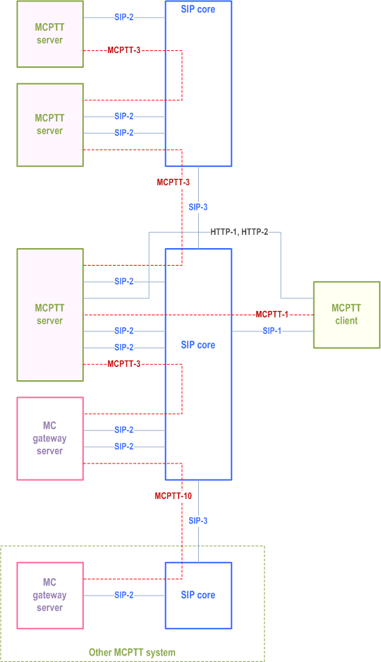
The MCPTT-1 reference point, which exists between the MCPTT client and the MCPTT server, is used for MCPTT application signalling for establishing a session in support of MCPTT. The MCPTT-1 reference point shall use the SIP-1 and SIP-2 reference points for transport and routing of SIP signalling. The MCPTT-1 reference point may use the HTTP-1 and HTTP-2 reference points.
The TMGI is communicated between the MCPTT server and the MCPTT client using the MCPTT-1 reference point.
Information that is reported to the MCPTT server from the MCPTT client shall be configurable at the application layer. This interface may include the area where a UE is currently located, described as ECGI of the serving and neighbouring cell(s), MBMS SAIs, MBSFN Area ID. This information comes from the broadcast by the local cell, e.g. from SIB1 and SIB15 (see TS 36.331) as decoded by the UE.
Messages supported on this interface may also include the MCPTT server providing the MCPTT client with information describing the mapping of transport resources to specific group calls.
7.5.2.3 Reference point MCPTT-2 (between the MCPTT server and the MCPTT user database) p. 26
The MCPTT-2 reference point, which exists between the MCPTT server and the MCPTT user database, is used by the MCPTT server to obtain information about a specific user. The MCPTT-2 reference point utilises a diameter management application protocol as defined in TS 29.283 and shall be intra-network.
7.5.2.4 Reference point MCPTT-3 (between the MCPTT server and the MCPTT server and between the MCPTT server and the MC gateway server) p. 26
The MCPTT-3 reference point exists between the MCPTT server and the MCPTT server and between the MCPTT server and the MC gateway server for MCPTT application signalling for establishing MCPTT sessions. The MCPTT-3 reference point shall use the SIP-2 reference point for transport and routing of signalling. If a pair of MCPTT servers, or an MCPTT server and an MC gateway server, are served by different SIP cores then the MCPTT-3 reference point shall also use the SIP-3 reference point for transport and routing of signalling. Floor control signalling and media are also transferred using the MCPTT-3 reference point.
7.5.2.5 Reference point MCPTT-4 (unicast between the floor control server and the floor participant) p. 26
The MCPTT-4 reference point, which exists between the floor control server in the MCPTT server and the floor participant in the MCPTT client, provides floor control signalling between the floor control server in the MCPTT server and the floor participant over a unicast bearer. The MCPTT-4 reference point uses the SGi reference point defined in TS 23.002.
7.5.2.6 Reference point MCPTT-5 (between the MCPTT server and the EPS) p. 26
The MCPTT-5 reference point, which exists between the MCPTT server and the EPS, is used, subject to the conditions below, by the MCPTT server to obtain unicast bearers with appropriate QoS from the EPS. It utilises the Rx interface of the EPS according to TS 23.203.
MCPTT-5 is not used when the MCPTT service provider and the PLMN operator do not have an operational agreement for QoS control to be provided directly from the MCPTT service provider domain.
MCPTT-5 may be used when the MCPTT service provider and the PLMN operator have an operational agreement where QoS control is provided directly from the MCPTT service provider domain.
7.5.2.7 Reference point MCPTT-6 (between the MCPTT server and the EPS) p. 26
The MCPTT-6 reference point, which exists between the MCPTT server and the EPS, is used to request the allocation and activation of multicast transport resources for MCPTT application usage. The MCPTT-6 reference point uses the MB2-C interface as defined in TS 29.468.
7.5.2.8 Reference point MCPTT-7 (unicast between the media distribution function and the media mixer) p. 27
The MCPTT-7 reference point, which exists between the media distribution function and the media mixer, is used to exchange unicast media between the media distribution function of the MCPTT server and the media mixer of the MCPTT client. The MCPTT-7 reference point uses the SGi reference point defined in TS 23.002.
7.5.2.9 Reference point MCPTT-8 (multicast between the media distribution function and the media mixer) p. 27
The MCPTT-8 reference point, which exists between the media distribution function and the media mixer, is used by the media distribution function of the MCPTT server to send multicast media to the media mixer of the MCPTT client. The MCPTT-8 reference point uses the MB2-U interface defined in TS 23.468.
7.5.2.10 Reference point MCPTT-9 (multicast between the floor control server and the floor participant) p. 27
The MCPTT-9 reference point, which exists between the floor control server and the floor participant, provides floor control signalling between the floor control server and the floor participant over a multicast bearer. The MCPTT-9 reference point uses the MB2-U interface defined in TS 23.468.
7.5.2.11 Reference point IWF-1 (between the MCPTT server and the interworking function to legacy systems) p. 27
The IWF-1 reference point is specified in TS 23.283.
7.5.2.12 Reference points of common services core used in the MCPTT service p. 27
The descriptions for reference points of the common services core are contained in the common functional architecture to support MC services specified in TS 23.280.
7.5.2.13 Reference point MCPTT-10 (between the MC gateway server and the MC gateway server in a different MCPTT system) |R15| p. 27
The MCPTT-10 reference point, which exists between the MC gateway server and the MC gateway server in an interconnected MCPTT system for MCPTT application signalling for establishing MCPTT sessions, shall use the SIP-3 reference point for transport and routing of signalling. Floor control signalling and media are also transferred using the MCPTT-10 reference point between interconnected MCPTT systems.
8 Identities p. 27
The MCPTT service specific identities (e.g. MCPTT ID, MCPTT group ID) are described in clause 8 of TS 23.280.
9 Application of functional model to deployments p. 27
The application of the functional model to deployments, and description of various deployment scenarios for the MCPTT service, can be found in clause 9 of TS 23.280.